


www.ti.com
EPWMxINT
EPWMxTZINT
EPWMxSOCA
EPWMxSOCB
EPWMxSYNCI
EPWMxSYNCO
Time-base (TB) module
Counter-compare (CC) module
Action-qualifier (AQ) module
Dead-band (DB) module
PWM-chopper (PC) module
Event-trigger (ET) module
Trip-zone (TZ) module
Peripheral bus
ePWM module
TZ1 to TZ6
EPWMxA
EPWMxB
PIE
ADC
GPIO
MUX
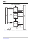
SubmoduleOverview
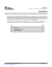
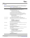
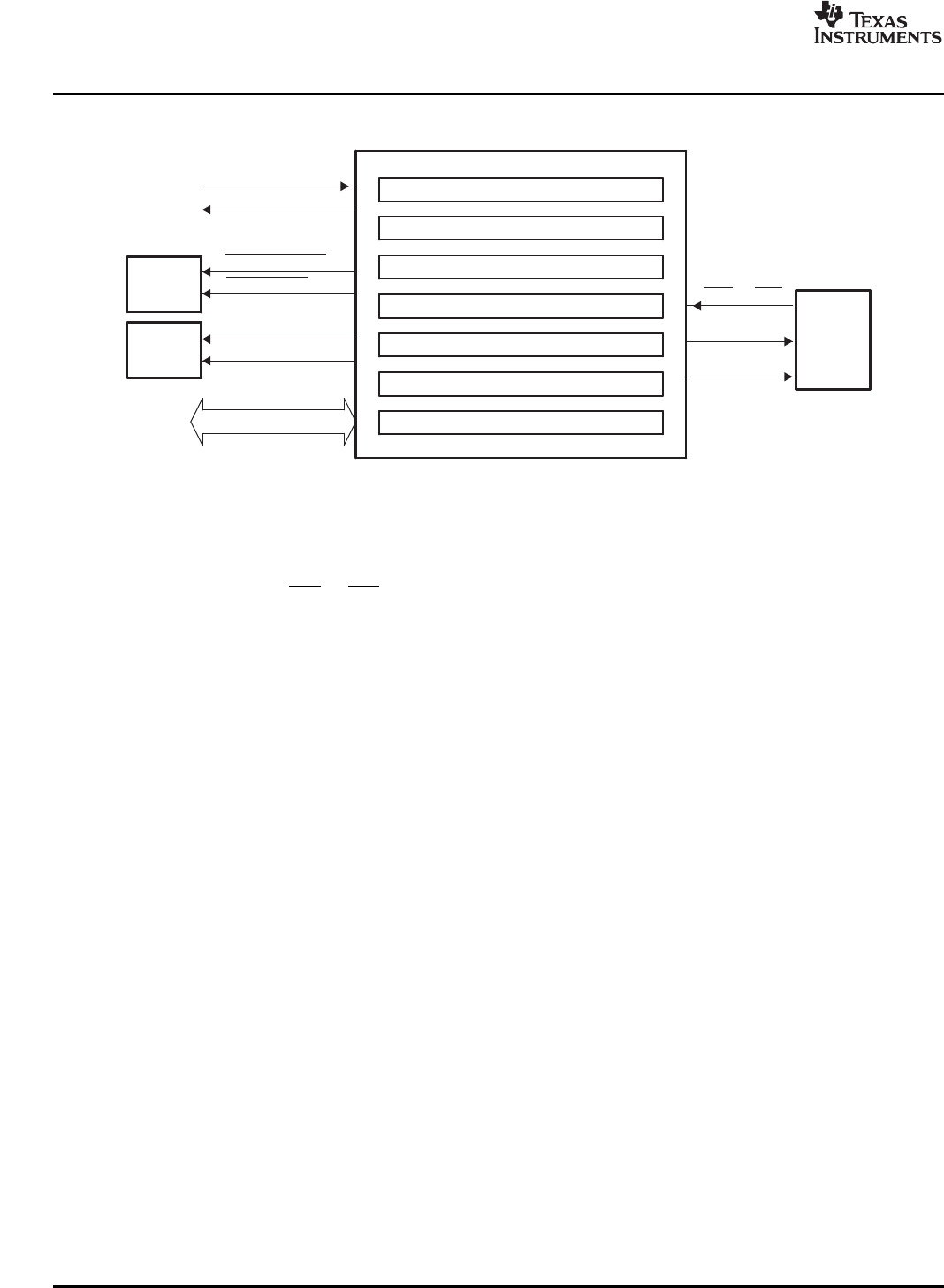
Figure1-2.SubmodulesandSignalConnectionsforanePWMModule
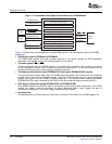
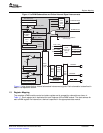
Figure1-3showsmoreinternaldetailsofasingleePWMmodule.ThemainsignalsusedbytheePWM
moduleare:
•PWMoutputsignals(EPWMxAandEPWMxB).
ThePWMoutputsignalsaremadeavailableexternaltothedevicethroughtheGPIOperipheral
describedinthesystemcontrolandinterruptsguideforyourdevice.
•Trip-zonesignals(TZ1toTZ6).
TheseinputsignalsalerttheePWMmoduleofanexternalfaultcondition.Eachmoduleonadevice
canbeconfiguredtoeitheruseorignoreanyofthetrip-zonesignals.Thetrip-zonesignalscanbe
configuredasasynchronousinputsthroughtheGPIOperipheral.
•Time-basesynchronizationinput(EPWMxSYNCI)andoutput(EPWMxSYNCO)signals.
ThesynchronizationsignalsdaisychaintheePWMmodulestogether.Eachmodulecanbeconfigured
toeitheruseorignoreitssynchronizationinput.Theclocksynchronizationinputandoutputsignalare
broughtouttopinsonlyforePWM1(ePWMmodule#1).ThesynchronizationoutputforePWM1
(EPWM1SYNCO)isalsoconnectedtotheSYNCIofthefirstenhancedcapturemodule(eCAP1).
•ADCstart-of-conversionsignals(EPWMxSOCAandEPWMxSOCB).
EachePWMmodulehastwoADCstartofconversionsignals(oneforeachsequencer).AnyePWM
modulecantriggerastartofconversionforeithersequencer.Whicheventtriggersthestartof
conversionisconfiguredintheEvent-TriggersubmoduleoftheePWM.
•PeripheralBus
Theperipheralbusis32-bitswideandallowsboth16-bitand32-bitwritestotheePWMregisterfile.
16IntroductionSPRU791D–November2004–RevisedOctober2007
SubmitDocumentationFeedback