


www.ti.com
0000
FFFFh
TBPRD
TBCTR[0-15]
time
CTR = PRD
(SycnOut)
Master Module
Φ2
Phase = 120°
0000
FFFFh
TBPRD
TBCTR[0-15]
time
SyncIn
Slave Module
TBPHS
600 600
600 600
200
200
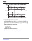
3.8Controllinga3-PhaseInterleavedDC/DCConverter
Controllinga3-PhaseInterleavedDC/DCConverter
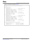
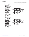
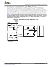
Figure3-12.TimingWaveformsAssociatedWithPhaseControlBetween2Modules
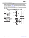
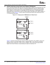
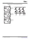
Apopularpowertopologythatmakesuseofphase-offsetbetweenmodulesisshowninFigure3-13.This
systemusesthreePWMmodules,withmodule1configuredasthemaster.Towork,thephase
relationshipbetweenadjacentmodulesmustbeF=120°.ThisisachievedbysettingtheslaveTBPHS
registers2and3withvaluesof1/3and2/3oftheperiodvalue,respectively.Forexample,iftheperiod
registerisloadedwithavalueof600counts,thenTBPHS(slave2)=200andTBPHS(slave3)=400.
Bothslavemodulesaresynchronizedtothemaster1module.
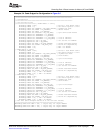
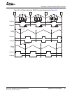
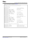
Thisconceptcanbeextendedtofourormorephases,bysettingtheTBPHSvaluesappropriately.The
followingformulagivestheTBPHSvaluesforNphases:
TBPHS(N,M)=(TBPRD/N)x(—1)
Where:
N=numberofphases
M=PWMmodulenumber
Forexample,forthe3-phasecase(N=3),TBPRD=600,
TBPHS(3,2)=(600/3)x(2-1)=200(i.e.,PhasevalueforSlavemodule2)
TBPHS(3,3)=400(i.e.,PhasevalueforSlavemodule3)
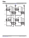
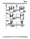
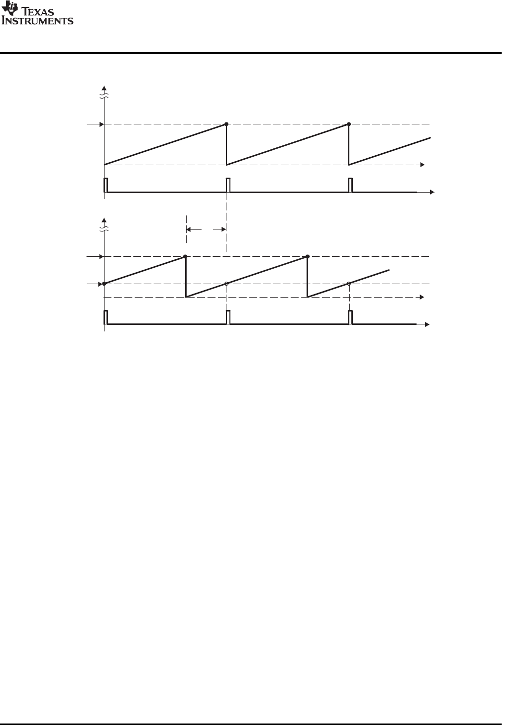
Figure3-14showsthewaveformsfortheconfigurationinFigure3-13.
SPRU791D–November2004–RevisedOctober2007ApplicationstoPowerTopologies85
SubmitDocumentationFeedback