


Purpose
1-2
1.1 Purpose
The ADS5102/3 EVM provides a platform for evaluating the ADS5102/3
analog-to-digital converter (ADC) under various signal, reference, and supply
conditions. Use this document in combination with the EVM schematic
diagram supplied.
1.2 EVM Basic Functions
Analog input to the ADC is provided via two external SMA connectors. The
single-ended input the user provides is converted into a differential signal at
the input of the device. One input uses a differential amplifier, while the other
input is transformer coupled.
The EVM provides an external SMA connection for input of the ADC clock. The
user can send this clock to the output connector with the digital data or provide
a second clock source to be sent in place of the ADC clock. This allows the user
to provide the required setup and hold times of the output data with respect to
the output clock. See the Clock Inputs section for the proper configuration and
operation.
Digital output from the EVM is via a 40-pin connector. The digital lines from the
ADC are buffered before going to this connector. More information on this
connector can be found in the ADC output section.
Power connections to the EVM are via banana jack sockets. Separate sockets
are provided for the analog and digital supply.
In addition to the internal reference provided by the ADS5102/3 device,
options are provided on the EVM to allow adjustment of the ADC references
via an onboard reference circuit. A precision voltage reference source, a
resistor network, and an operational amplifier (op amp) provide the
ADS5102/3 device reference voltages REFT and REFB.
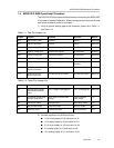
1.3 Power Requirements
The EVM can be powered directly with a single 1.8-V supply if using the
module with transformer coupled input, internal reference source, and 1.8-V
logic outputs.
A voltage of 3.3 V is required for the DRVDD power input to provide 3.3-V logic
outputs. A voltage of ±5 V is required if using external references and/or
differential amplifier input. Provision has also been made to allow the EVM to
be powered with independent 1.8-V analog and digital supplies to provide
higher performance.
Voltage Limits
Exceeding the maximum input voltages can damage EVM
components. Undervoltage may cause improper operation of
some or all of the EVM components.