


Schematic Diagram
3-4
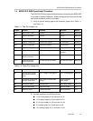
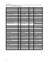
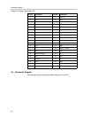
Table 3–2.Output Connector J15
J15 Pin Description J15 Pin Description
1 NC 21 Data Bit 6
2 GND 22 GND
3 Output clock 23 Data Bit 5
4 GND 24 GND
5 NC 25 Data Bit 4
6 GND 26 GND
7 NC 27 Data Bit 3
8 GND 28 GND
9 NC 29 Data Bit 2
10 GND 30 GND
11 NC 31 Data Bit 1
12 GND 32 GND
13 NC 33 Data Bit 0 (MSB)
14 GND 34 GND
15 Data Bit 9 (MSB) 35 NC
16 GND 36 GND
17 Data Bit 8 37 NC
18 GND 38 GND
19 Data Bit 7 39 NC
20 GND 40 GND
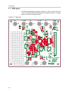
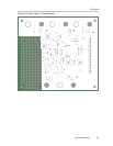
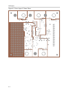
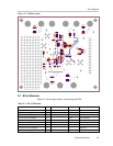
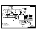
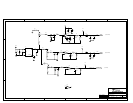
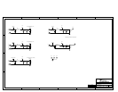
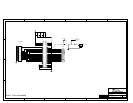
3.2 Schematic Diagram
The following figures show the schematic diagram for the EVM.