


4ConnectingtoFPGAPlatforms
4.1TSW1100
4.2TSW1200
www.ti.com
ConnectingtoFPGAPlatforms
TheADS61xx/ADS61B23EVMprovidesseveralconnectionoptionstomatetheEVMtovariousFPGA
developmentplatformsandFPGA-basedcaptureboards.
UsingtheaccompanyingCMOSbreakoutboard,userscaneasilymateTI'sTSW1100captureboardto
theADS61xx/ADS61B23EVM.SimplyconnectthebreakoutboardtotheJ2(Channel2)connectoronthe
TSW1100.Fromanorientationstandpoint,theXilinx™FPGAfacestheADCwhencorrectlyconfigured.
BeforeusingtheTSW1100tocaptureADCdataforthefirsttime,usersshouldupdatetheTSW1100
Supported_ADCs.txtfile.TheyshouldexploretheaccompanyingADS61xx/ADS61B23softwareCDand
replacetheinstalledTSW1100Supported_ADC.txtfilewiththeonefoundontheCD;thisfileadds
TSW1100supportforboththeADS612xandADS614x.
Finally,usersshouldensurethattheADC61xxEVMisconfiguredinCMOSoutputmode.Inaddition,the
TSW1100representsaloadgreaterthan5pFandassuch,usersshouldconsiderboostingtheCMOS
drivestrengthbyusingtheTISPIControlsoftware.Inmanycases,theboostingofthedrivestrengthis
notrequiredtoperformvaliddatacaptureswhenusingtheTSW1100;thisisanoptionalstep.
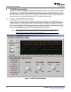
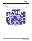
TheADS61xx/ADS61B23nativelyplugsintotheTSW1200FPGAplatform.Inmostcircumstances,the
TSW1200functionsasadeserializer.However,theVirtex™-4FPGAcanbereprogrammedtoallowthe
ultimateinflexiblesolutionprototyping.ForuserswishingtoapplyFPGAcontroloverthe
ADS61xx/ADS61B23SPIinterface,movethesurface-mountjumpersintothefollowingpositions.
•MovethejumperonJ2(SEN)tothe1–2position,andremoveR7andpopulateR62witha0-Ω
resistor.
•MovethejumperonJ7(SCLK)tothe1–2position,andremoveR20whileinstallingthe0-Ωresistorto
R63.
•MovethejumperonJ6(SDATA)tothe1–2position,andremoveR19whileinstallingthe0-Ωresistor
toR64.
•RemoveR18.
•MovethejumperonJ3toposition1–2toconfiguretheADCintotheSPIoperationmode(serial
interfacemode).
SLAU206B–September2007–RevisedApril200813
SubmitDocumentationFeedback