


3-2
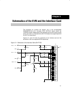
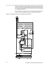
Schematics of the EVM and the Interface Card
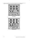
Because the interface card was originally designed for universal application
purposes, some of the components shown in the schematic above may not be
on the board when shipped with this EVM kit. Refer to the bill of materials table
for a complete component list.
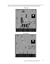
A key is installed in the edge connector on the interface board (SLVP155) to
ensure that the hot-swap board can only be inserted the right direction.
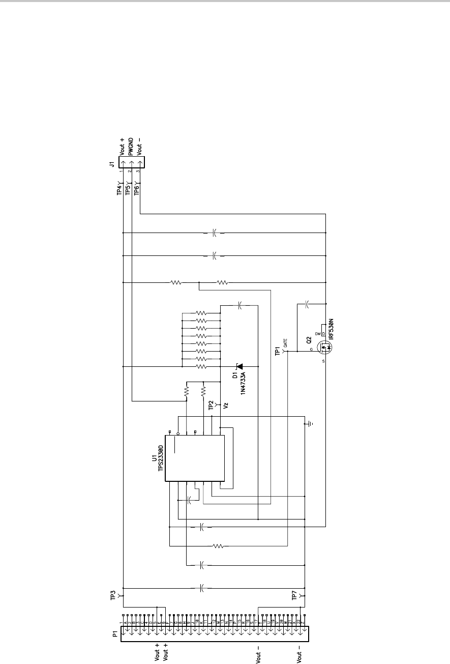
Figure 3–2. Schematic of the 48-V Hot-Swap EVM (SLVP184)
1
GATE
2
DGND
3
TIMER
4
VREG
5
VSENSE
6
AGND
7
ISENSE
8
IN
9
AGND
10
ISET
11
FAULT
12
PWRGD
13
ENABLE
14
DISCH
+
C1
C6
0.1 µF
C1
0.001 µF
R8
0 Ω
C4
4.7 µF
C3
0.1 µF
R4
5.1 kΩ
56 kΩ
56 kΩ
56 kΩ
56 kΩ
56 kΩ
56 kΩ
56 kΩ
56 kΩ
R14
R13
R12
R11
R10
R7
R2
R1
C2
0.1 µF
R5
890 kΩ
R6
33 kΩ
C7
0.1 µF
C5
100 µF
C8
0.1 µF