


4-1
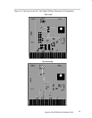
Layouts of the EVM and the Interface Card
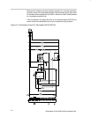
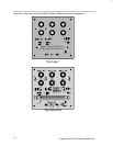
The following figures illustrate the placements of the components and the
top-layer layouts for both the 48-V hot-swap EVM and the interface card
respectively. All the components are placed on the top layers except for the
0.1-µF capacitor (C8) on SLVP184 that has now been included on the bottom
layer. (The bottom layers are mainly ground planes).
Chapter 4