


5-1
Setup of the EVM
For proper operation of the EVM, one 48-V power supply, and a voltage meter
or an oscilloscope are required.
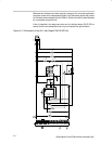
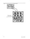
Refer to the setup diagram in Figure 5–1 and follow these steps for hot plug
testing:
1) Verify that the power-supply voltage is set at 48 V. Make sure the supply
has the capability to provide the current loads need. Turn off the supply.
2) Connect a meter or oscilloscope to monitor the voltages from Vout+ (pin 1
of J1) to Vout– (pin 2 of J1) on the SLVP184 board.
3) Plug the supply into the interface card; connect the supply from IN1 to
ground. Then turn on the power supply. Check the voltage from VIN1 to
GND, which should be about 48 V.
4) Plug the hot-swap board (SLVP184) into the interface board (SLVP155).
The key installed between pins 1 and 2 of the edge connector insures that
the board can only be inserted in the correct direction.
5) Test points or headers are provided for oscilloscope probes and/or multi-
meters. Read the voltage from the multimeters connecting from Vout+ to
Vout– on SLVP184. The value of the meter should be about 48 V. Other-
wise, the board may have problems or the testing may not be correct.
6) Unplug the SLVP184 board from the interface card.
More evaluations such as adding loads to the output rails, can be performed
by following procedures similar to those presented above.
Chapter 5