


TUSB3410 EVM Setup
2-2
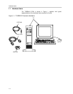
2.1 TUSB3410 EVM Setup
The TUSB3410 general-purpose EVM is designed to support many USB
applications. The EVM comes in a default configuration that requires no
additional components on the EVM. A full description of the TUSB3410 device
is specified in the data manual. The PC must be running a USB-capable
operating system. Configure the EVM if required, based on desired settings
specified later in this section. Use a standard USB cable to connect the
TUSB3410 EVM to a downstream port of the PC or a USB hub tier.
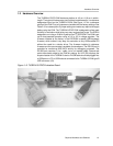
2.2 Interfaces and USB Ports
The EVM uses a standard type-B connector for the upstream port. An I
2
C
serial interface is provided to access an I
2
C EEPROM. A UART port is
embedded in the microcontroller and is connected to the RS-232 port on the
EVM. The RS-232 port connection can not be disabled by using the jumpers.
See jumper settings for more details. There are four buttons and four LEDs on
the EVM that can be used as general-purpose inputs and outputs to evaluate
how the system works.
2.3 Power Supply
The TUSB3410 EVM uses USB bus power as its power supply.
2.4 Buttons
Table 2–1.Button Description
Button Button Description
SW1 System reset
SW2 Wakes up system if system is in suspend mode
SW3 General-purpose input, pulls P3.0 low if pressed
SW4 General-purpose input, pulls P3.1 low if pressed
SW5 General-purpose input, pulls P3.4 low if pressed
SW6 General-purpose input, pulls P3.3 low if pressed
2.5 Light Emitting Diodes (LEDs)
Table 2–2.LED Description
LED LED Description
D2 LED on indicates that the EVM is suspended
LED off indicates that EVM is not suspended
D3 General-purpose output, indicates status of P3.0 (RXD)
D4 General-purpose output, indicates status of P3.1 (TXD)
D5 General-purpose output, indicates status of P3.4
D6 General-purpose output, indicates status of P3.3