


Jumpers
2-3
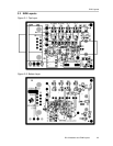
EVM Operation
2.6 Jumpers
Table 2–3 is provided to help set up and configure the EVM platform jumpers
for the desired mode of operation. The EVM can download firmware code from
the PC through a loading program (may or may not be supplied with your EVM)
or from an I
2
C EEPROM. JP2 and JP3 are used to connect P3.0 and P3.1 to
D3 and D4 respectively. JP4 is for separating the SCL pin of the I
2
C EEPROM
from SCL of the TUSB3410.
Table 2–3.Jumper Description
Jumper Jumper Description
JP1 Installed: connect suspend LED to SUSP pin of TUSB3410
JP2 Installed: connect LED D4 and SW4 to P3.1 (GPIO_TXD)
JP3 Installed: connect LED D3 and SW3 to P3.0 (GPIO_RXD)
JP4 Installed: connect SCL of I
2
C EEPROM to SCL of TUSB3410 for normal operation
Uninstalled: downloads firmware from USB instead of I
2
C EEPROM
2.7 EEPROM
The I
2
C EEPROM is used to provide application-specific firmware. The
TUSB3410 automatically reads the EEPROM at power up via the I
2
C bus. A
header must be added to the application firmware before loading it into the
EEPROM. See the TUSB3410 data manual for a description of the header
definition. The header can be generated automatically using the I
2
C
header-generation utility software provided with the device.
The EVM ships with a preprogrammed EEPROM that has keyboard controller
firmware. It enumerates properly when connected to a USB host.