


TS 870 TRANSFER SWITCH
PM062 REV 5 08/05/05 8 Thomson Technology
4.2. TYPICAL COMMISSIONING PROCEDURES
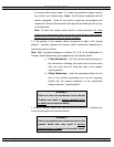
CAUTION:
Commissioning procedures must be performed by qualified
personnel only. Ensure the Automatic Transfer Switch
(ATS) Control Circuit Isolation Plug is disconnected prior to
energizing the supply sources. Manually place the transfer
switch mechanism in the neutral position prior to applying
power. Failure to do so may result in equipment failure or
personal injury.
Note: The TYPICAL AUTOMATIC TRANSFER SWITCH COMMISSIONING
PROCEDURES MODEL SERIES TS 870 (attached as “Appendix A ”) is provided for
general information only pertaining to typical site installations and applications. Contact
Thomson Technology for further information as may be required.
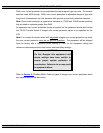
Note: An optional hand held, plug-in Service Display Module (SDM) is available for the TSC
80 Transfer Controller. The SDM module provides an LCD screen to display additional
detailed information on the operation and settings of the TSC 80 controller for simplified
servicing/trouble shooting procedures. For detailed information, refer to the separate SDM
module instruction manual (PM065).
5. GENERAL THEORY OF OPERATION
5.1. STANDARD AUTOMATIC TRANSFER SWITCH
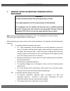
5.1.1. NORMAL OPERATION
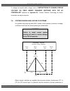
When utility supply voltage drops below a preset nominal value (adjustable from 70%
to 100% of nominal) on any phase, an engine start delay circuit is initiated and the
transfer to utility supply signal will be removed (i.e. contact opening). Following
expiry of the engine start delay period (adjustable from 0 to 60 sec.) an engine start
signal (contact closure) will be given.
Once the engine starts, the transfer switch controller will monitor the generator
voltage and frequency levels. Once the generator voltage and frequency rises above
preset values (adjustable from 70% to 95% of nominal), the engine warm-up timer