


TS 870 TRANSFER SWITCH
PM062 REV 5 08/05/05 5 Thomson Technology
the supply source be arranged such that the phase of highest potential with respect
to ground is not connected to the power supply inputs to the controller (A Phase for
both supplies). Failure to do so will result in equipment damage.
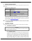
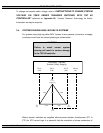
Per NEC Article 384-3 (f) “The B phase shall be that phase having the higher voltage
to ground on a 3-phase, 4-wire delta connected systems.”
3.5. REMOTE START CONTACT FIELD WIRING
As a minimum, the remote engine start control field wiring shall conform to the local
regulatory authority on electrical installations. Field wiring of a remote start contact
from a transfer switch to a control panel should conform to the following guidelines to
avoid possible controller malfunction and/or damage.
3.5.1. Minimum #14 AWG (2.5mm
2
) wire size shall be used for distances up to 100ft
(30m)
1
). For distances exceeding 100 ft. (30m) consult Thomson Technology
3.5.2. Remote start contact wires should be run in a separate conduit.
3.5.3. Avoid wiring near AC power cables to prevent pick-up of induced voltages.
3.5.4. An interposing relay may be required if field-wiring distance is excessively
long (i.e. greater than 100 feet (30m)) and/or if a remote contact has a
resistance of greater than 5.0 ohms.
3.5.5. The remote start contact must be voltage free (i.e. dry contact). The use of a
“powered” contact will damage the transfer controller.
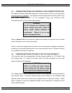
3.6. DIELECTRIC TESTING
Do not perform any high voltage dielectric testing on the transfer switch with the TSC
80 controller connected into the circuit as serious damage will occur to the controller.
All AC control fuses and control circuit isolation plugs connected to the TSC 80 must
be removed if high voltage dielectric testing is performed on the transfer switch.
3.7. INSTALLATION OF OPEN TYPE TRANSFER SWITCHES
Please refer to the factory for additional information.
4. GENERAL DESCRIPTION
Thomson Technology TS 870 series of Automatic Transfer Switches employ two mechanically
interlocked enclosed contact power switching units and a microprocessor based controller to
automatically transfer system load to a generator supply in the event of a utility supply failure.