


TOSHIBA
6.0 UPS Control Interface
6.2 RS-232C Serial Communication Interface
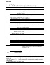
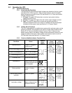
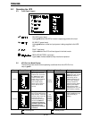
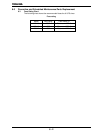
The available data from the UPS, via RS-232C communication, is shown below:
Output voltage
Output current
Operating conditions Battery voltage
Input frequency
Output frequency
Utility power OK
Low battery voltage detected
UPS operating status UPS in BYPASS mode
(described as ‘yes’ or ‘no’) UPS in NORMAL mode
Input and output frequency synchronized
UPS ‘fault’ occurred
DC bus overcurrent
DC bus overvoltage
DC bus undervoltage
'Fault’ details Input overcurrent
(described as ‘occurred’ Overheat
or ‘not occurred’) Overload being timed
Overload (allowable time exceeded)
Output overvoltage (during NORMAL mode)
Output undervoltage (during NORMAL mode)
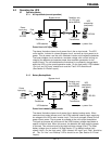
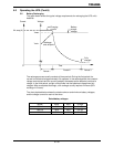
6.2.1 UPS Shutdown (via RS-232C)
When the UPS is operating from its internal batteries, a ‘shutdown’ order can be
sent to the UPS telling it to turn OFF after a user-specified amount of time. This
function can allow you to stop discharging the UPS batteries after an orderly
system shutdown has been completed. The UPS can be programmed to turn
OFF up to 8 minutes after the ‘shutdown’ command is given. This command can
be cancelled before the specified time has elapsed.
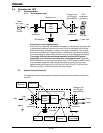
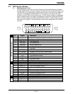
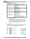
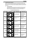
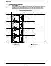
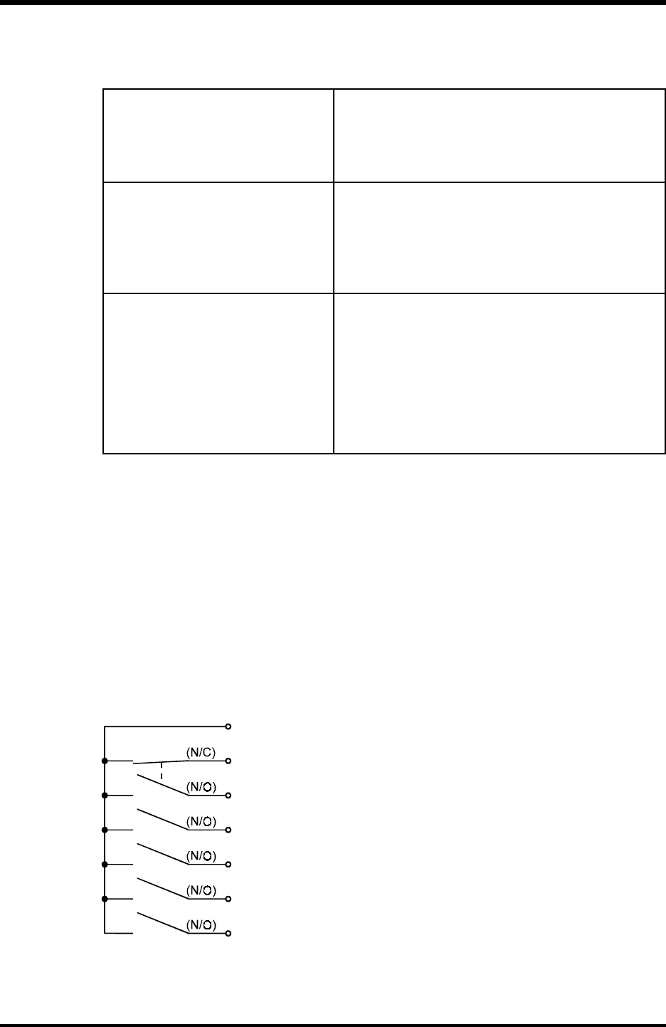
6.3 Dry Contact Interface
The Dry Contact interface uses pins 16 trough 22. Pins 24 and 25 are used for the
shutdown function. The following schematic shows the contact state and pin assignments
for each signal output along with the associated DB25 connector pinout.
16 Dry Contact common
17
Notes:
Battery Backup 1) Pin “switches are shown
18 in their
inactive states
(ex. if battery voltage is
19 Battery voltage “low” low then pin 19 will be
connected to pin 16)
20 UPS “on”
2) Contacts are rated as
21 Bypass “on” follows:
dc: 48V, 0.1A
22 Fault detect signal ac: 30Vrms (42V-peak)
0.07A(0.1A-peak)
6 - 2
}