


25
1600EP Series Instruction Manual
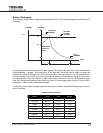
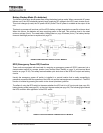
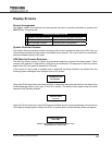
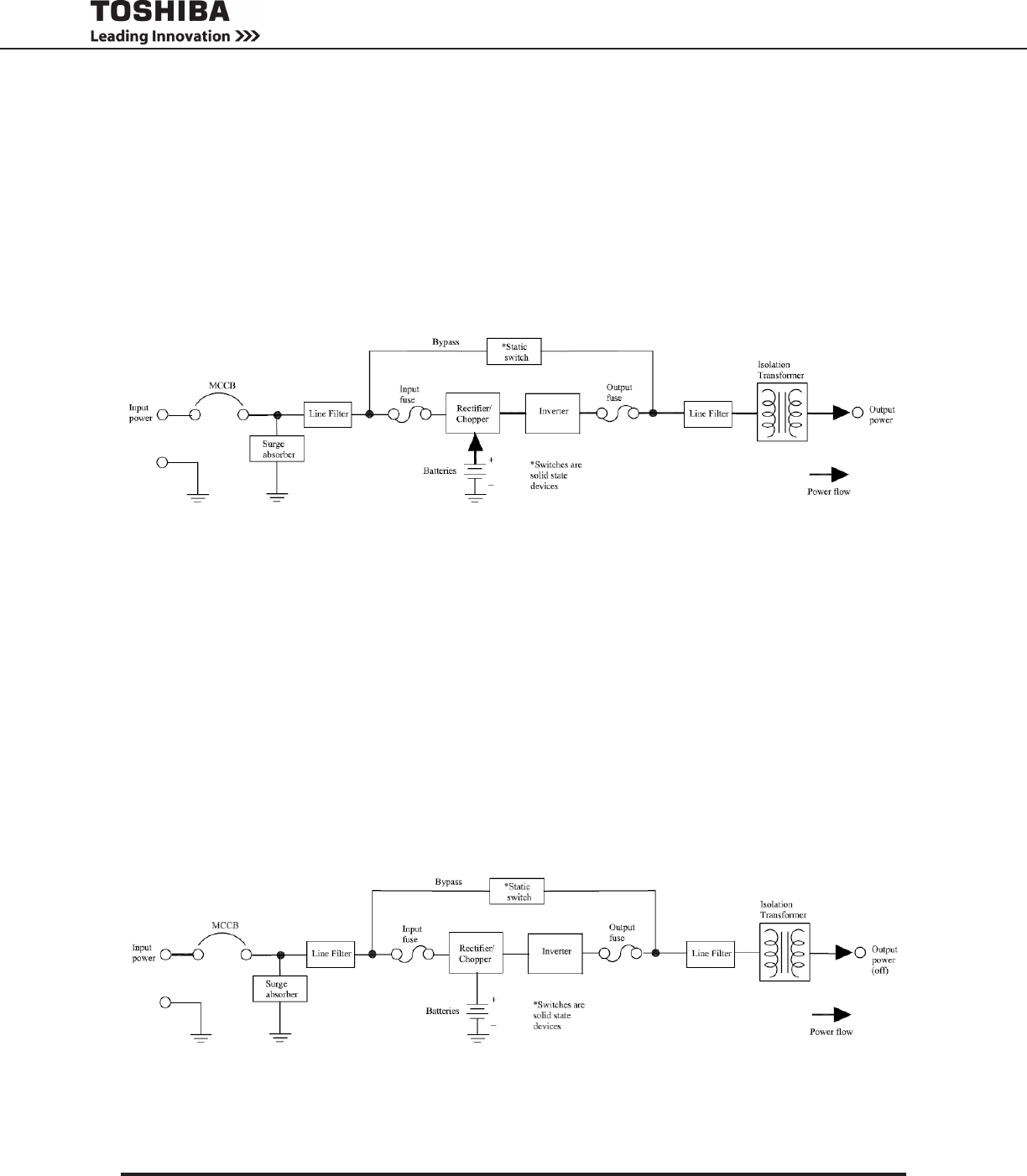
Battery Backup Mode (On batteries)
The following illustration shows power ow during the battery backup mode. When commercial AC power
failures occur, the UPS’s batteries instantly begin supplying DC voltage to the UPS’s main inverter circuit.
This circuit changes (inverts) the DC power into AC power. The AC power is available at the output of the
unit.
This back-up process will continue until the UPS’s battery voltage drops below a specic minimum level.
When this occurs, the batteries will stop supplying power to the load. This minimum level is the rated
minimum voltage (Vmin). The rated battery voltage chart on page 23 shows (Vmin). The battery backup
time and discharge process is explained on page 23.
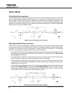
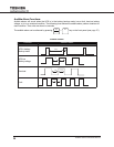
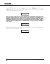
EPO (Emergency Power Off) Function
These units are equipped with terminals for receiving an emergency power-off (EPO) command via a
closed-contact switch at a remote location (see Terminal Block Details on page 11 and terminal block
location on page 37-38). This safety feature enables quick shut-down of the UPS’s AC output and battery
circuits.
Usually the emergency power off switch is installed in a central location that is easily accessible to
personnel concerned with the operation of the UPS unit and the load equipment connected to it. The EPO
function is initiated by pressing the switch to the closed (shutdown) position.
The effect of using the EPO switch is the same whether the UPS unit is in AC input mode (see page 24),
battery backup mode (see page 25), or the circuit bypass mode (see page 24). The following gure shows
the UPS condition after application of the EPO switch.
POWER FLOW IN BATTERY BACKUP FOR ALL MODELS
POWER FLOW AFTER AN EPO COMMAND FOR ALL MODELS