


E6581402c
-11-
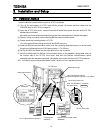
3.5. Wiring of a control terminal
Observe the following when wiring.
-Use0.3to1.5mm
2
solid/stranded wire (AWG 22 to 16) for control cables.
- Remove the s heath of a cable about 7mm (6mm for FLA, FLB, FLC and G /E) from the end of cable.
- Use a flat-headed screwdriver with its blade 0.6mm in thickness and 3.5mm in width.
- Screw tightening torque for the t erminal block screws should be 0.5 t o 0.6Nm.
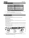
N.B.: Keep the control signal cables 20cm or more separate from the power cables to prevent from
malfunctioning due to electromagnetic noise.
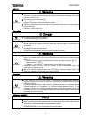
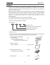
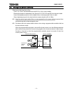
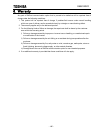
N.B.: Provide an inter-lock system stated in below, when using a programmable controller that has
the open collector output.
When the programmable controller is t urned off with the inverter is on, the difference between
each control power potential will c ause wrong signals to the inverter as shown in below figure.
Provide an inter-lock so that t he programmable controller cannot be turned off when the
inverter power is alive.
COM
+24V
Inverte
r
internal +24V
External
+24V supply
VF-FS1 + BCN002ZProgrammable controller
Input terminal
Fuse blowout
detection
circuit
Fuse