


E6581402c
-8-
3. Installation and Setup
3.1. Installation method
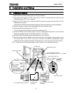
Install the BACnet communication option to VF-FS1 as follows.
(1) Turn off the input power o f VF-FS1 and wait for at least 10 minutes and then check that the
CHARGE lamp on VF-FS1 is n o longer lit.
(2) Open the VF-FS1 front cover, remove the terminal board fixing screw and take off the VF-FS1
standard terminal board.
(Be careful not to lose the t erminal board fixing screw when removed since it may be used again.)
(3) Perform wiring an inverter before installing BACnet communication option.
(4) Please a ttach the insulating sheet in VF-FS1.
(Fix to the terminal board fixing screw hole and PWB catch pin.)
(5) Install the BACnet communication option over the insulating sheet and secure it with the board
fixing screw (tightening torque of M3 tapping screw: 0.7 to 0.8Nm).
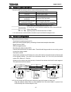
(6) Set up the S W of the board with the input terminal for sink or source.
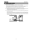
(7) Stick the cabling label for BACnet communication option on the standard cabling label stuck on
the reverse side of the VF-FS1 front cover. And stick the BACnet communication option
nameplate near the standard nameplate. (Be careful not to c over slits on the VF-FS1 enclosure.
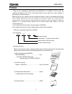
N.B.: To install or remove the terminal board, make it slide in or out in parallel with board.
VF-FS1 name plate
BACnet communication option
(
BCN002Z
)
VF-FS1 Standard terminal board
VF-FS1 unit
Stick the BCN002Z nameplate
like bellow figure.
BCN002Z
Insulating seat
(attached)
Board c atching pin
Board fixing screw hole
BCN002Z
Terminal board fixing scre w
(M3 screw tightening torque: 0 .7 to 0.8Nm)
Cabling label position
Example