


GD-1220/1221 © 2006 - 2008 TOSHIBA TEC CORPORATION All rights reserved
ELECTRICAL CIRCUITS
4 - 6
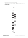
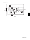
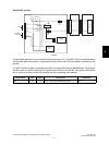
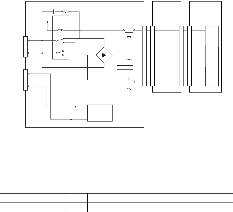
4.2.3 Dial pulse generation circuit
NA/TW models
Fig. 4-6
The dial pulse generation circuit consists of the diode bridge (DB1), photocoupler (PC1), the ASIC
(IC23) on the MAIN board and the other peripheral devices. It generates the dial pulses in the FAX
transmission and dialing to the outside.
The ASIC makes the CML1 signal become HIGH to connect the line to the MODEM side. To generate
the dial pulse, the ASIC makes the LD1 signal become HIGH to turn ON Q53. This allows the photo-
coupler to come on and the current flows through the DB1 to send the dial pulses to the line.
Signal Name Type Active Description Destination
LD1 O H Line 1 Dial Pulse Generation Signal Q53
CML1
LD1
3
4
4
3
1
2
AG
Q51
CN10
CN11
Lb
La
Line
0
1
0
1
3
10
8
12
4
9
1
+12V
RLY2
CML relay
4
3
3
4
144
143
FAX board
NCU board
IC23
ASIC
Ring signal
detection
circuit
CN9
CN262
-
PC1
DB1
+
~
~
Q53
SG
+5V
a2
b2
External
telephone
3
4
C5 R4
CN5
CN5
27
61
27
61
MAIN board