


32
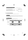
8. INPUT OUTPUT SIGNAL SPECIFICATOINS
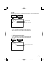
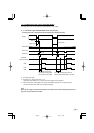
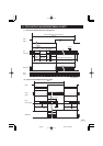
( 1 )HD Input Specifications
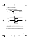
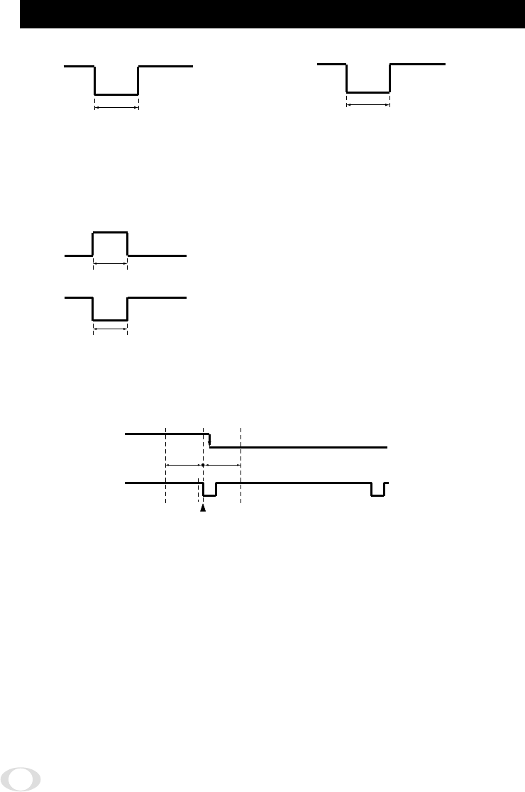
The phase relationship of the external HD and VD should correspond to the center phase (i.e., the external HD falling
edge) as illustrated in the above diagram.
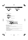
External VD falling edge:
Please input within about 100 clock cycles of the standard center phase.
Note that V sync of the video is output with a delay of about 1H from the external VD at the time of reset-restart and
the external trigger mode.
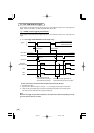
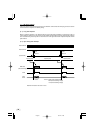
In the normal mode:
Continuously with the HD period of 31.78 ms and VD period of 16.68 ms (partial scanning 120fps : 8.33ms, partial
scanning 180fps : 5.56ms).
Phase timing is as illustrated in the above diagram (with only the falling edge applicable).
In the reset-restart/external trigger mode:
Continuously with the HD period of 31.78 ms. VD (reset) is at an arbitrary timing with the phase of HD being within the
standard of the above diagram.
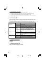
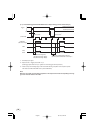
( 2 )VD Input Specifications
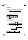
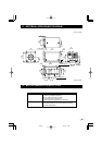
( 3 )Trigger Pulse Specifications
2.0 µs to 5.0 µs
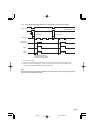
( 6 )External HD/VD Input Phase Specifications
(Positive polarity mode)
(Negative polarity mode)
More than 2 µs
More than 2 µs
5H to 21H
100 100
External HD
rising edge
Center
Unit : Clock
1 clk=40.74 nsec
External HD
05.3.14, 14:58Page 32