


No. EJL- 106A
Density (Consistency) Meter LQ500
Introduction
The LQ500 density (consistency) meter uses
microwave phase shift technology to determine
concentrations of solids in the material to be measured
flowing through pipes. It can perform a stable and
realtime density (consistency) measurement because
this technology is not affected by flow velocity along
with fluid color, and also is not easily affected by
contaminants and low process pressure rate. As the
LQ500 has no moving parts, it is reliable and virtually
maintenance free.
Since the output of the LQ500 is theoretically linear, it
can be applied to a wide range of density (consistency)
measurement.
<Notice>
The LQ500 requires a full pipe to measure the
density (consistency). Contact Toshiba before
installation in the following cases:
<Possibility of unfilled condition>
(a) When it is installed at the discharge of a pump.
(b) When installation is horizontal, and unfilled
condition occurs inside the pipe.
(c) A process where the pipe becomes unfilled
when the operation is stopped.
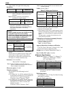
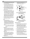
Cable for power suppl
y
(Detector/converter)
Ground resistance
100 ohm or less
Density
(
consistency
)
measurement output 4-20mA
Cable for communication
(Detector/converter)
A
C power supply
DI / DO
External Sync control
contact in
p
ut
Figure
1. LQ500 Configuration Diagram
■
Standard Configuration
• Density (Consistency) Meter: 1 set
(Detector and converter separate mounted)
• Accessories: 1 set (see Table 1 below)
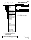
Table 1. Standard Accessories
Items Specifications Quantity
Power supply
cable
Between detector and
converter (*1)
10 m
(32.8 ft)
Communication
cable
Between detector and
converter (*1)
10 m
(32.8 ft)
Fuse
2A(T), 250 V
(glass tube, 5.2 dia. x 20 mm)
2
Document Instruction manual 1
Note 1: Need to prepare a power supply cable for the
LQ500.
Refer to the section of cable specifications at the
overall specifications in detail.
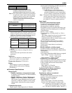
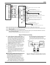
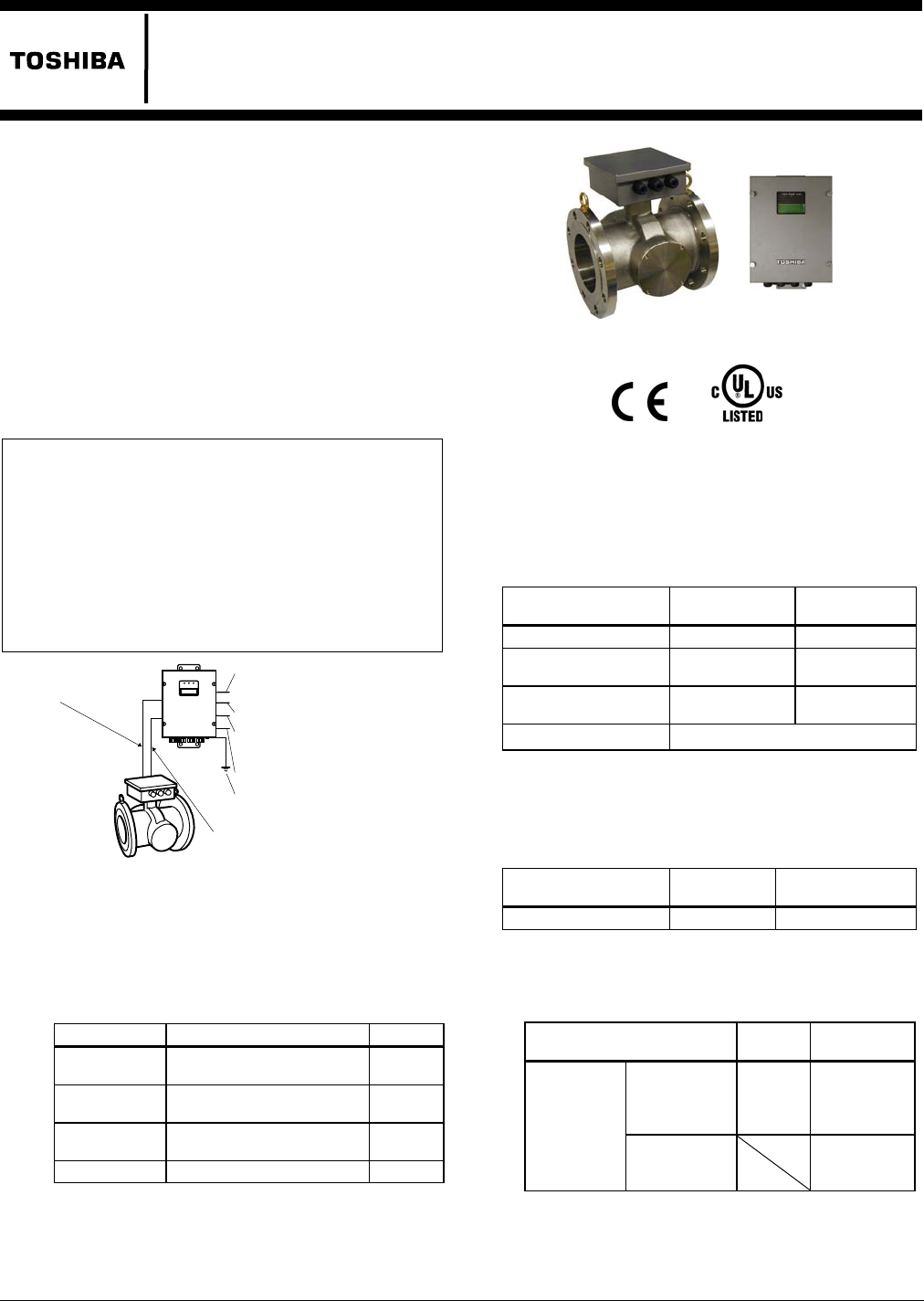
Figure 2. LQ500 Density (consistency) Meter
Specifications
■
Overall Specifications
Measurement method:
Microwave
phase difference method
Measurement
range:
Meter size 50 mm (2”)
80 to 300 mm
(3” to 12”)
Span (*2) 2 to 50 %TS (*1) 1 to 50%TS (*1)
Lower limit setting
range (4 mA)
0 to 48%TS 0 to 49%TS
Upper limit setting
range (20 mA)
2 to 50%TS 1 to 50%TS
Setting increments 0.1%TS
*1 TS: Total Solids
*2 Span = Upper range – Lower range
*3 The material to be measured must be fluid
and be filled evenly with no voids.
Repeatability:
Meter size 50 mm (2”)
80 to 300 mm
(3” to 12”)
Repeatability ±0.02%TS ±0.01%TS
Note 1 : Above values are the results of commuting ability
in the phase measurements of the converter.
Note 2 : Density (consistency) determination
repeatability for sample reagent;
Meter size
50 mm
(2”)
80 to 300 mm
(3” to 12”)
For the full
scale value of
2%TS or
greater
±2%FS ±2%FS
Density
(consistency)
determination
repeatability
For the full
scale value of
less than 2%TS
±4%FS
*The characteristics of sample reagent has errors due
to sample tests such as uneven density (consistency)
distribution.
*Full scale is the maximum value in the measurement