


LQ500
6
(7) Install an adjustable piping mechanism if there
is a possibility that the detector pipe may not fit
between mating flanges.
(8) Install the LQ500 in a place where enough
water pressure is applied. Therefore, it is
recommended that the LQ500 be installed as
far away as possible from the pipe outlet
opened to atmosphere. This is to prevent the
effects of air being trapped in the liquid.
(9) If there is a possibility of no liquid flow or
uneven liquid distribution occurring when a
pump is off, use an external synch control
signal to operate the LQ500 only when the
pump is working.
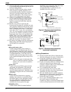
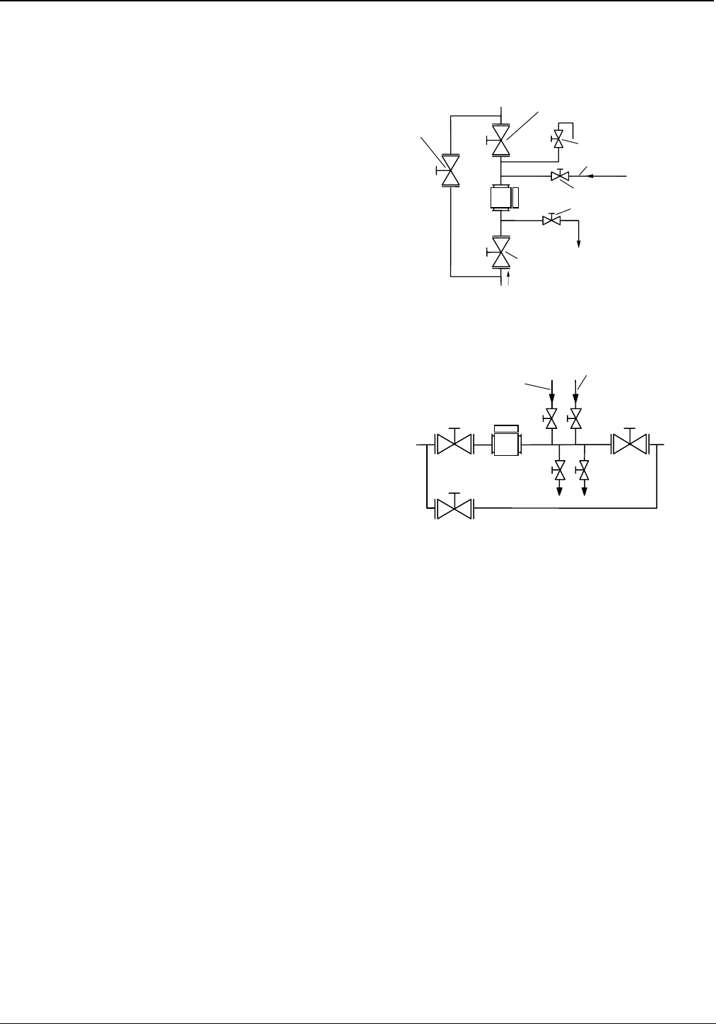
(10) Provide a stop valve at upstream and
downstream of the detector, and between stop
valves and the LQ500 provide the four valves
described below with a stop valve attached to
each: 1) sampling outlet valve; 2) zero point
water inlet valve; 3) vent valve; and 4) drain
valve. If it is not possible to stop the fluid at the
point where the LQ500 is installed, provide a
bypass pipe with a stop valve provided in the
middle. These valves are needed to drain the
fluid from the detector
pipe and fill it with
drinking water (density or consistency 0%) to
adjust the zero point. See Figures 6 and 7.
(11) Use gaskets for piping of the size conformed to
flange rating and of the material appropriate
for the liquid to be measured.
NOTE:
• Zero point water valve:
Used to supply drinking water (density or
consistency 0%) to the detector pipe for zero
point adjustment. Install this valve at the top of
the pipe in the case of horizontal installation. It
is recommended that a 1-inch ball valve be
installed on the top of the pipe and zero point
water supplied through this inlet using a vinyl
hose etc.
Note: If valve water pipe is connected to this
valve, air cannot be extracted. Therefore,
another valve (vent valve) is needed to
extract air.
• Vent valve:
Used to vent process fluids to open air when
performing zero adjustment. This helps the
drinking water (density or consistency 0%)
enter the detector pipe easily. Install this valve
on the top of the pipe in the case of horizontal
installation.
• Drain valve:
Used to drain the fluids before supplying
drinking water (density or consistency 0%) to
the detector pipe for zero adjustment. Install
this valve at the lowest point of the pipe. It is
recommended that a 1-inch ball valve be
installed at the lowest point of the pipe.
• Sampling valve:
Used to extract fluids for manual analysis.
Install this valve to the side of the pipe in the
case of horizontal installation. It is
recommended that a 1-inch ball valve be
installed to the side of the pipe.
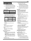
Stop
valve
Bypass
pipe
Zero point water valve
Flow direction
(from down to up directions)
Drain pipe
V
ent valve
Drain valve
Stop valve
LQ500
Stop valve
Zero point water pipe
Figure 6. Recommended Installation
(vertical installation)
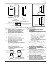
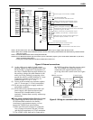
Stop valve
Vent valve
Zero point
water valve
LQ500
Stop valve
Bypass pipe
Drain
valve
Sampling
valve
Stop valve
Figure 7. Recommended Installation
(horizontal installation)
■
Wiring Precautions
(1) Provide a switch and a fuse to isolate the unit
from the mains power for ease of maintenance.
(2) Ground the LQ500 with 100 ohm or less
ground resistance. Do not use a common
ground shared by other power equipment.
(3) Use the accessorious cables for communication
and power supply between detector and
converter. Connect cables to the terminals that
match the marking on the cables.
(4) Use a sheathed cable with 2mm
2
cross-sectional area for AC power cable.
(5) The cables should be free from vibration and
should have no slack in the cables.
(6) Wire the LQ500 output in conduit separated
from those of AC power cable, control signals,
alarm signal or other cables which could
become the source of noise.
(7) Use a 2-wire shielded sheathed cable to wire
the LQ500 output (4-20mAdc) and
conductivity signal. Ground the shielded cable
on the receiving instrument side for both cable.