


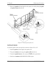
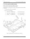

4.16 Cover assembly and Base assembly 4 Replacement Procedures
Installing the Cover assembly and Base assembly
To install the cover assembly and base assembly, follow the steps below and refer to Figure
4-28 to 4-30.
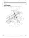
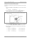
1. Place the cover assembly on the base assembly and secure them with the following
screws.
• M2.5×10B FLAT HEAD screw ×4
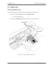
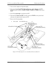
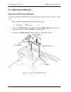
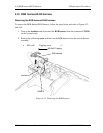
2. Insert the core to the Smart card FFC and connect the Smart card FFC to the
connector CN2170 on the system board. Stick the acetate tape in place.
NOTE: Set the core next to the connector portion of the Smart card FFC and stick the
acetate tape on them.
A
cetate tape
Core
Connector
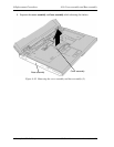
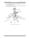
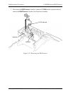
3. Connect the touch pad FFC, Bluetooth harness, camera harness and LCD harness
to the connector CN9550, CN4440, CN9540 and CN5000 on the system board.
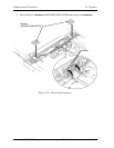
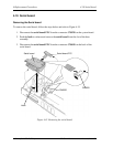
4. Turn over the computer and secure the cover assembly and base assembly with the
following screws.
• M2.5×16B FLAT HEAD screw ×3 (“16” in the figure 4-28)
• M2.5×10B FLAT HEAD screw ×8 (“10” in the figure 4-28)
• M2.5×5B FLAT HEAD screw ×2 (“5” in the figure 4-28)
TECRA M10 Maintenance Manual (960-685) [CONFIDENTIAL] 4-49