Chapter 1 Hardware Overview
16
15
14
13
17
13
1 2
12
3
11
18
4
5 67
8
10
9
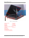
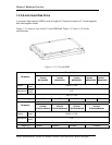
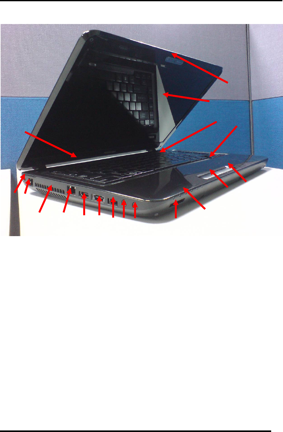
Figure 1-1-1 left of the computer
1. Security Lock Hole 13. Touch Pad
2. RJ11 Port 14. Keyboard
3. FAN Hole 15. LCD Panel
4. RL45 Port 16. Web camera
5. HDMI Port 17. Power Button
6. E-SATA Port (integrated a USB Port)
7. USB Port 18. Hall-sensor
8. Ext. MIC Port
9. Earphone Port
10. Card Reader Port
11. Touch Pad Control Left Button
12. Touch Pad Control Right Button
Satellite L600/L640/L645, Satellite Pro L600/Pro L640/Pro L645 Maintenance Manual (960-Q08)


