


3.10 Peripheral 3 Diagnostic Programs
3.9 Communication (COMM)
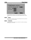
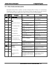
Subtest 01 LPT
This test item is to check whether there is open or short circuit issue in the external
pins by looping back the external pins, controlling the voltage of each data pin,
control pin and status pin.
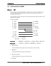
The test requires an external connector to insert into the tested LPT port. Below is the
connector's description.
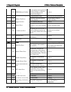
Fixture Description:
(
9
)
+ PD7
(
15
)
-ERRO
R
(
5
)
+ PD3
(
1
)
-ST
R
OBE
(
10
)
-AC
K
(
8
)
+ PD6
(
14
)
-AUTFD
(
7
)
+ PD5
(
13
)
(
6
)
+ PD4
(
16
)
-PINIT
(
2
)
+PD0
(
11
)
+ BUSY
(
3
)
+ PD1
(
17
)
-SLIN
(
4
)
+ PD2
(
12
)
+ PE
Note: (1)~(17) -------- Pin number
PD0~ PD7--------Data Line
Status Line -------- –ERROR(S3), +SELECT(S4), –ACK(S6), +PE(S5), +BUSY(S7)
Control Line-------- –AUTFD(C1), –PINIT(C2), -STROBE(C0), –SLIN(C3)
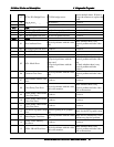
1. Register Check
Check whether the data register and control register works normally.
2. IRQ Check
Check whether LPT interrupt works normally.
3. External Loop back
Check whether there is open or short circuit issue.
4. ECP Mode
Satellite A100/A105 / TECRA A7 Maintenance Manual 59