


7. Operation in Status Monitor Mode
7-2
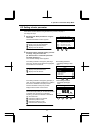
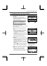
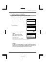
7. 1 Displaying details of an item monitored
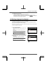
1 Select/confirm the desired item using the
control dial.
(Ex. Select/confirm “Output current”)
The monitor window of the item selected appears.
* Depending on the item selected, no monitor
window may be displayed.
Functions of function keys
: Brings you to the Top View Mode.
: Brings you to the Parameter Setup Mode.
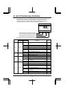
How to use monitor windows
Monitor windows can be broadly classified under the
following three types.
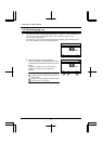
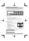
<Type of window 1: Displays a value and a
graph>
This type of window displays an analog value,
such as an output frequency, output current or
output voltage. (Ex. “Output current”)
It displays the current value both numerically and
in a graph form.
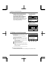
In addition, the minimum allowable value (min)
and the maximum allowable value (max) are also
displayed at the bottom of the window.
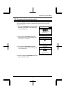
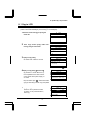
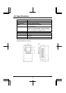
<Type of window 2: Displays information in a
graph form>
This type of window displays input/output terminal
information and a life alarm in a graph form. (Ex.
“Input terminal : S4, S3...R, F”)
It displays the ON/OFF status of each terminal
signal and the ON/OFF status of an alarm signal in
a graph form.
If the arrow
is moved to a terminal or alarm
symbol, the name of the function assigned to the
terminal or the name of the alarm is displayed.
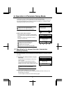
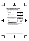
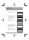
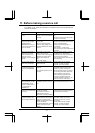
<Type of window 3: Displays information in a list
form>
This type of window displays detailed trip
information. (Ex. Past trip # 1 (latest))
It displays the conditions under which the inverter
was operated at the occurrence of tripping.
Status Monitor Mode
In
p
ut terminal 1 : S4,S3…R,F
ON
OFF
Forward run
To
p
Prm
S4 S3 S2 S1 RES ST R F
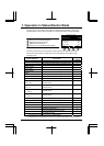
Past trip # 1
(
latest
)
E :Emer
g
enc
y
sto
p
Sequence number 1
Output frequency 25.0Hz
Rotative direction FWD
Frequency reference 30.0Hz
Output current 40%
To
p
Prm
Output current
min=0 max=185
To
p
Prm
22%
Status Monitor Mode
Out
p
ut current
min=0 max=185
Top Prm
22%
Status Monitor Mode
* This illustration shows the
information displayed when the
LCD panel is connected to an
VF-AS1 inverter.
F1 F4
F1
F4