


Chapter 4 Replacement Procedures
Satellite T110 / Sa tellite Pro T110 / PORTEGE T110 Maintenance Manual (960-Q08)
Figure 4-10-2 Loose the screws........................................................................................... 35
Figure 4-10-3 Remove the touchpad and touchpad board................................................... 36
Figure 4-11-1 Positions of I/O boards ................................................................................. 38
Figure 4-11-2 Remove the screws from I/O boards............................................................. 39
Figure 4-12-1 Remove the system board............................................................................. 40
Figure 4-12-2 Remove the RTC battery-step_1................................................................... 42
Figure 4-12-3 Remove the RTC battery-step_2................................................................... 43
Figure 4-12-4 Install the RTC Battery................................................................................. 44
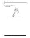
Figure 4-13-1 Remove the CPU heat sink ........................................................................... 45
Figure 4-14-1 Remove the display mask ............................................................................. 47
Figure 4-14-2 Remove screws securing the LCD................................................................ 48
Figure 4-14-3 Remove the LCD .......................................................................................... 48
Figure 4-14-4 Remove the harness ...................................................................................... 49
Figure 4-14-5 Remove the LCD hinge ................................................................................ 49
Figure 4-15-1 Remove EMI tape on the web camera module ............................................. 51
Figure 4-15-2 Remove the connector of Web Camera module ........................................... 51
Figure 4-15-3 Peel off the glue of Web Camera module..................................................... 52
Figure 4-16-1 Intel &AMD Thermal grease on North Bridge and CPU ............................. 53
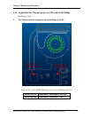
Figure 4-16-2 Apply silicon grease for North Bridge and CPU .......................................... 54
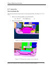
Figure 4-17-1 Remove the securing screws at left side ....................................................... 55
Figure 4-17-2 Remove the securing screws at right side..................................................... 55
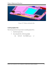
Figure 4-17-3 Remove the Speaker Box.............................................................................. 56
Figure 4-18-1 Remove the HDD cable ................................................................................ 57