


TIC-LF494B
3
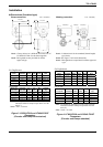
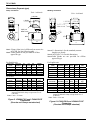
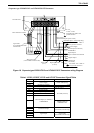
Model LF610 and LF612 converters
Input signals
Analog signal — the voltage signal from detector,
proportional to process flow rate (for LF612
separate type converter).
Digital input DI (opt.)
Signal type: 20 to 30Vdc voltage signal
Input resistance: 2.7kΩ
Number of inputs: one point
DI function — One of the following functions
can be assigned to the optional DI signal.
Range switching — Selects either the higher or
lower range in the unidirectional or
bidirectional 2-range setting.
Totalizer control — Starts and stops the built-in
totalizer.
Fixed-value outputs —Outputs fixed-values for
current and pulse outputs.
Zero adjustment — Executes zero adjustment
(on-stream at zero flow rate).
Output signals
Current output:
4–20mAdc (load resistance 0 to 750Ω)
Note: The current output cannot be used with
the PROFIBUS-PA ccommunication.
Digital outputs — One point (std.) and one more
point is optionally available as follows.
Digital output DO1 (std.):
Output type: Transistor open collector
Number of outputs: One point
Output capacity: 30Vdc, 200mA maximum
Digital output DO2 (opt.):
Output type: Solidstate relay output (non
polarity)
Number of outputs: One point
Output capacity: 150Vdc, 150mA maximum
or 150Vac (peak to peak), 100mA maximum
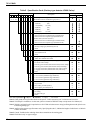
DO1 and DO2 functions — One of the following
functions can be assigned to DO1 (std.) and/or
DO2 (opt.)
• Pulse output (available only for DO1,DO2)
Pulse rate: 3.6 to 36,000,000 pulses/hr (DO1)
3.6 to 360,000 pulses/hr (DO2)
(Over 3,600,000 pulses/hr, auto-setting)
Pulse width: 0.5 to 500ms (but less than half of
the period for 100% flow rate)
Note: The same and simultaneous pulse is not
available between DO1 and DO2.)
• Multi-range selection outputs (Note 1)
• High, High high, Low, and/or Low low alarm
outputs (Note 2)
• Empty pipe alarm output
• Digital Output Active Status (DO1 and DO2)
(Note 2)
• Preset count output
• Converter failure alarm output
Note 1: Two outputs (DO1 and DO2) are needed
for 4-range switching and forward/reverse
2-range switching.
Note 2: Normal Open (default set) or Normal
Close is selected for alarm outputs when
programming.
When power failure occurs, unit will be fault to
Normal Open.
Communications output:
• HART (std.) — Digital signal is superimposed
on 4–20mAdc current signal as follows:
Conforms to HART protocol
Load resistance: 240 to 750Ω
Load capacitance: 0.25µF maximum
Load inductance: 4mH maximum
• PROFIBUS (opt.)
Protocol : PROFIBUS-PA
Baud rate : 31.25kbps
Bus voltage : 9-30VDC
Consumption electric current of bus:less than 16mA
Manufacture Ident-No. : 093B
HEX
Standard Ident-No. : 9740
HEX
Slave address : 0-126 (Default address is 126)
Profile : Profile Ver.3.01 for Process Control
Devices
Function blocks : AI(Flow)×1 , Totalizer×1
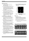
LCD display: Full dot-matrix 128×128 dot LCD
display (back-light provided)
The data on the LCD inside the converter can
rotate to 90, 180, and 270 degrees by a software,
without rotating the indicator itself. (Combined
type only)
Parameter settings — Parameters can be set as
follows:
• IR Switches: Three key switches are provided to
set configuration parameters.
• Digital communication: The AF900 hand-held
terminal or PROFIBUS is needed to set
parameters.
•Zero adjustment: Zero point adjustment can be
started by pressing the switch in the converter.
•Damping: 0.5 to 60 seconds (selectable in one
second increments)
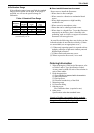
“Field re-verification”
Mag-Prover – Toshiba’s
Zero span calibration tool allows unit to be
re-calibrated and verified using an internal
software program. (For more information contact
Toshiba International Corp.)
Conditions when power fails:
Parameter setting values are stored in non-volatile
memory and the values will be restored when the
power returns to normal condition. The outputs
and display will remain as follows when power
fails.
• Current output: 0mAdc