


25
9. LED Indicators
The ETH-100 unit contains many different LED indicators, each of which conveys
important information about the status of the unit, connected drives and Ethernet
network. These LEDs and their functions are summarized here.
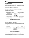
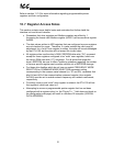
9.1 Module and Ethernet Indicators
The module and Ethernet indicators are located between the MMI port and the
Channel A drive port. Figure 8 indicates the functions of these LEDs (perspective is
with MMI port to the left of the LEDs).
MS (Module Status)
Currently reserved
NS (Network Status)
Currently reserved
LNK (Ethernet LiNK)
Solid green when valid
network link exists
ACT (Ethernet ACTivity)
Flashes red when network
activity is detected
Figure 8: Module and Ethernet Indicators
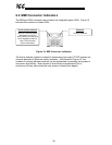
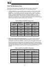
9.2 Drive Connector Indicators
Each drive communication channel RJ45 connector contains two integrated green
LEDs. Figure 9 indicates the functions of these LEDs.
Network Access
Blinks in 0.1s-long bursts
when channel is accessed
by Ethernet client
Drive Link
Solid green when a logical
connection exists with the
attached drive
Figure 9: Drive Connector Indicators
The Network Access indicator is useful for confirming that a specific drive channel is
being accessed correctly by the Ethernet client (master), while the Drive Link
indicator provides an easy method of determining that the ETH-100 and drive are
successfully exchanging data, independent of Ethernet activity.