


29
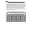
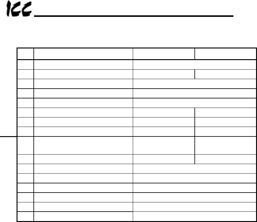
Table 2 : Example Status Word (ASD Register 0xFE01) Format
Bit Function 0 1
15 Reserved --
14 Faulted status Not faulted Faulted
13 Reserved --
12 Reserved --
11 Reserved --
10 Run / stop status Stopped Running
9 Forward / reverse status Forward Reverse
High Byte
8 Jog status Not jogging Jogging
7 DC injection braking status Not DC injection
braking
DC injection
braking
6 Accel / decel #1/#2 status #1 #2
5 Reserved --
4 Reserved --
3 Reserved --
2 Reserved --
1 Reserved --
Low Byte
0 Reserved --
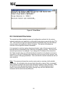
10.4 Register Remap Function
Some Modbus client software does not allow access to more than 10,000 Modbus
holding registers. As the standard ETH-100 mapping provides a simple 1-to-1
correspondence between Modbus holding registers and ASD registers (ASD register
number + 1 = Modbus holding register number), this can cause certain critical ASD
registers to be inaccessible from these clients. Specifically, Toshiba drives typically
place communication control registers and status registers in the 0xFAxx to 0xFFxx
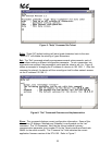
ASD register region. For example, “Communication Frequency Command” is
typically assigned to ASD register number 0xFA01, which is accessible via Modbus
holding register 0xFA01 + 1 = 0xFA02, which is 64002 in decimal. As this Modbus
holding register number is higher than 10,000, this register would not be accessible
via register-limited clients unless the ETH-100 performed register remapping.
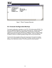
“Remap OFF” (default setting) does not modify the register mapping between the
ASD registers and the Modbus holding registers: a simple 1-to-1 correspondence
exists. “Remap ON” modifies the ASD register mapping slightly to allow access to
the drive’s critical control and status registers by Modbus clients that are limited to
accessing 10,000 holding registers max.
With the Remap parameter set to “ON”, the ETH-100 will add 0xF000 (61440
10
) to
incoming ASD register accesses between 0x0A00 and 0x0FFF (Modbus holding
registers 0x0A01 – 0x1000). In this way, register-limited clients need only write to
Modbus holding register 0x0A02 (2562
10
) to set the Communication Frequency
Command. Similarly, “Current Output Frequency” is typically located at ASD register