


7
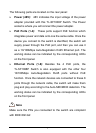
The following parts are located on the rear panel:
¾ Power (48V): 48V indicates the input voltage of the power
adapter provided with this TL-SF1008P Switch. The Power
socket is where you will connect the power adapter.
¾ PoE Ports (1-4): These ports support PoE function which
integrates power and data onto one the same cable. Once the
device you connect to the switch is identified, the switch will
supply power through the PoE port, and then you can use it
as a 10/100Mbps Auto-Negotiation RJ45 Ethernet port. The
working status can be indicated by the corresponding LEDs
on the front panel.
¾ Ethernet Ports (1-8): Besides the 4 PoE ports, the
TL-SF1008P Switch is also equipped with the other four
10/100Mbps Auto-Negotiation RJ45 ports without PoE
function. Once the network devices are connected to these 8
ports through the network cable, the switch will make them
plug and play according to the Auto-MDI/MDIX detection. The
working status can be indicated by the corresponding LEDs
on the front panel.
Note
Make sure the PDs you connected to the switch are complaint
with IEEE 802.3af.