


TL-SF2109P/TL-SF2117P/TL-SL2226P Ethernet Smart Switch User Guide
Chapter 3: Identifying External Components
This Chapter describes the front panel, rear panel and LED indicators of the Switch.
Cautions:
All the pictures are based on the TL-SF2109P in the manual. The others are similar with
the TL-SF2109P.
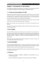
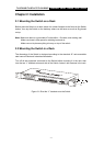
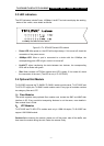
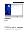
3.1 Front Panel
The front panel of the TL- SF2109P consists of switch LED indicators, 8 10/100Mbps
RJ-45 ports, and 1 serial port Connect the female of the power cord head here.
10/100Mbps Fast Ethernet Smart Switch
Console
Figure 3-1 TL- SF2109P Switch Front Panel sketch
Serial port: Config the system by the serial cable (more details in chapter 4)
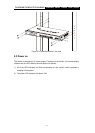
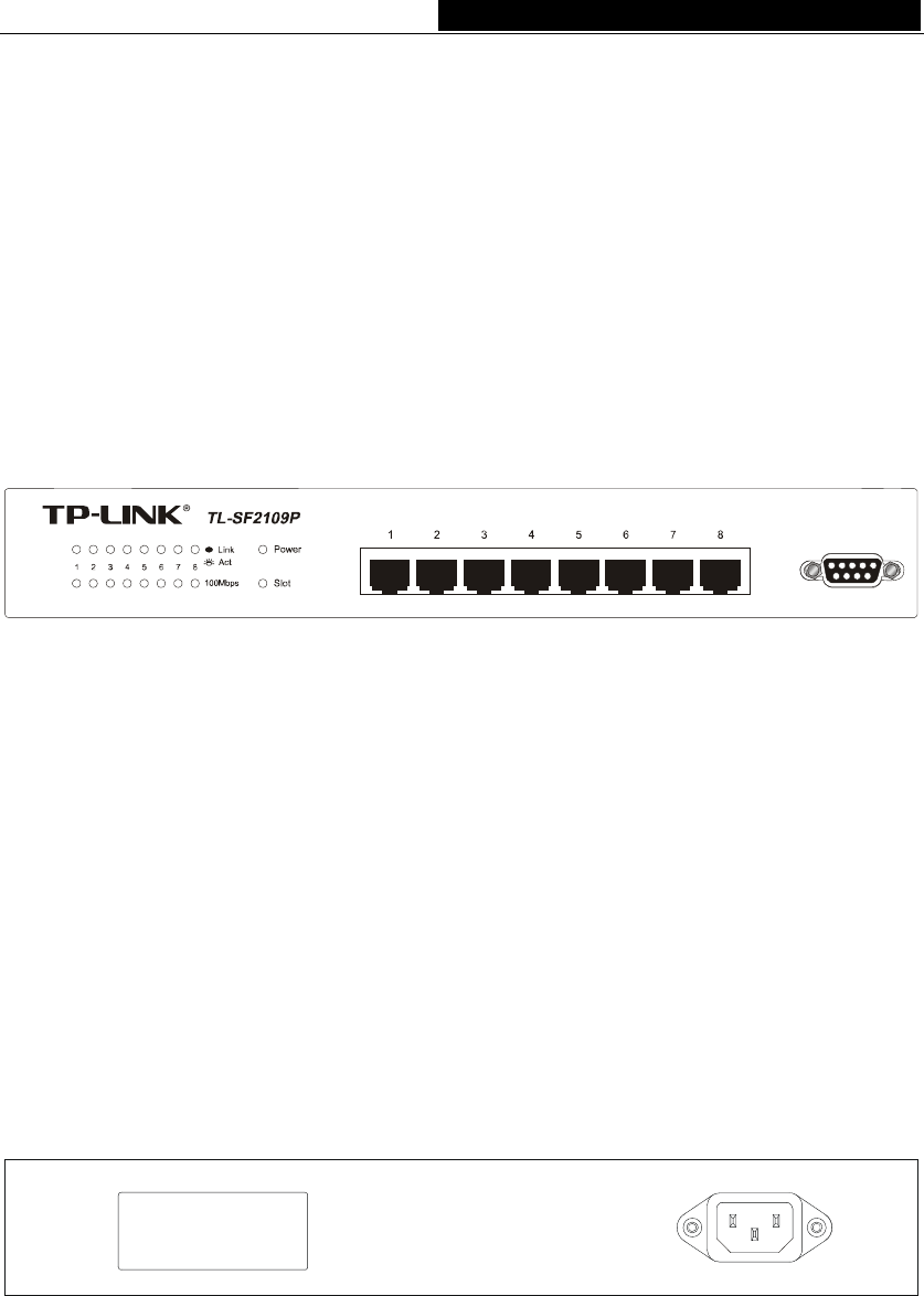
3.2 Rear Panel
The rear panel of the TL-SF2109P only features a power receptacle, which is an AC
power receptacle , and 1 extension slots. Connect the female of the power cord head
here, and the male head to the AC power outlet.
Extension slot: This is a optional module slot which can connect to a 100M
UTP/fiber (Tl-Sf2109P and TL-SF2117P) or a 1000M fiber module or 10/100/1000M
UTP module card(TL-Sl2226P).
Slot
Figure 3-2 TL- SF2109P Switch Rear Panel sketch
Power connector: This is a 3-Phase power socket, Plug the connector with a
100~240VAC/50-60Hz power supply.
- 6 -