


9
Web Smart Gigabit Switch Family User's Guide
TL-SG2109WEB/TL-SL2210WEB/TL-SL2218WEB/TL-SL2428WEB/TL-SL2452WEB
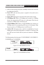
1) LEDs lie at the left side of the panel (1000Mbps Link/Act LED of the SFP
lie at right side of the SFP).
2) Power LED: solid red when power is supplied to the switch and is
operating normally.
3) System LED: ashing green when CPU of the switch works normally.
4) 10/100Mbps LED: When a 10/100Mbps port connect to a 100Mbps
device, the corresponding LED turns on in solid green; When the port
connects to a 10Mbps device, the LED turns off.
5) 10/100/1000Mbps LED: When a 10/100/1000Mbps port connect to a
1000Mbps device, the corresponding LED turns on in solid green; When
the port connect to a 10/100Mbps device, the LED turns off.
6) Link/Act LED: Solid green when a valid link is established on the port;
Flashes green when packet transmission or reception is occurring on the
port. (SFP port has Link/Act LED only and must connect to 1000Mbps
device.)
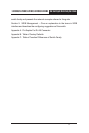
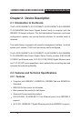
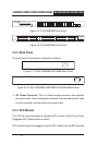
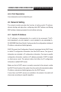
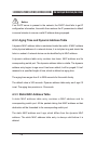
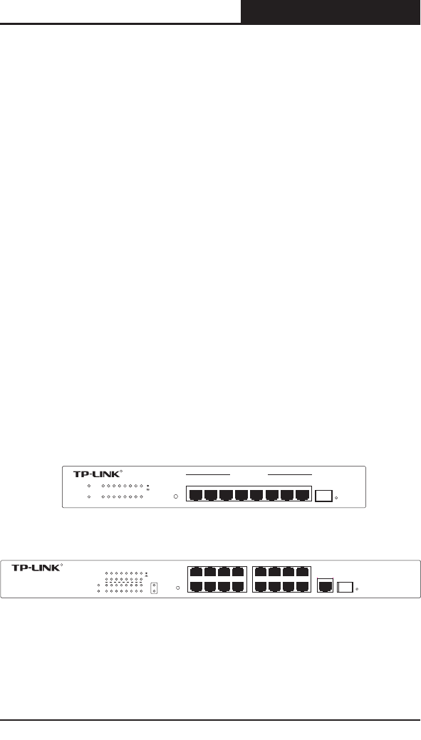
The following shows the front panel of TL-SG2109WEB, TL-SL2218WEB, TL-
SL2428WEB and TL-SL2452WEB:
1 3 5 7
2 4
6 8
SFP
1 2 3 4
5
6 7 8
8+1 Gigabit SwitchWeb-Smart
TL-SG2109WEB
10/100/1000Mbps
1000Mbps
RESET
Power
System
Link
Act
1000M
Link/Act
R
Figure 3-3 TL-SG2109WEB Front Panel
10 12 14 16
9
11
13 15
1
3 5 7
2 4 6 8
SFP
16+2G Gigabit Web-Smart Switch
Power
1000Mbps
2 4 6 8 10121416
1 3 5 7 9 111315
Link/Act
GIGA
System
TL-SL2218WEB
GIGA
Link/Act
RESET
Link
Act
100Mbps
R
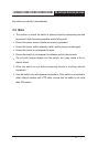
Figure 3-4 TL-SL2218WEB Front Panel