


63
Web Smart Gigabit Switch Family User's Guide
TL-SG2109WEB/TL-SL2210WEB/TL-SL2218WEB/TL-SL2428WEB/TL-SL2452WEB
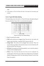
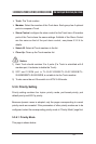
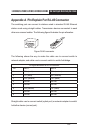
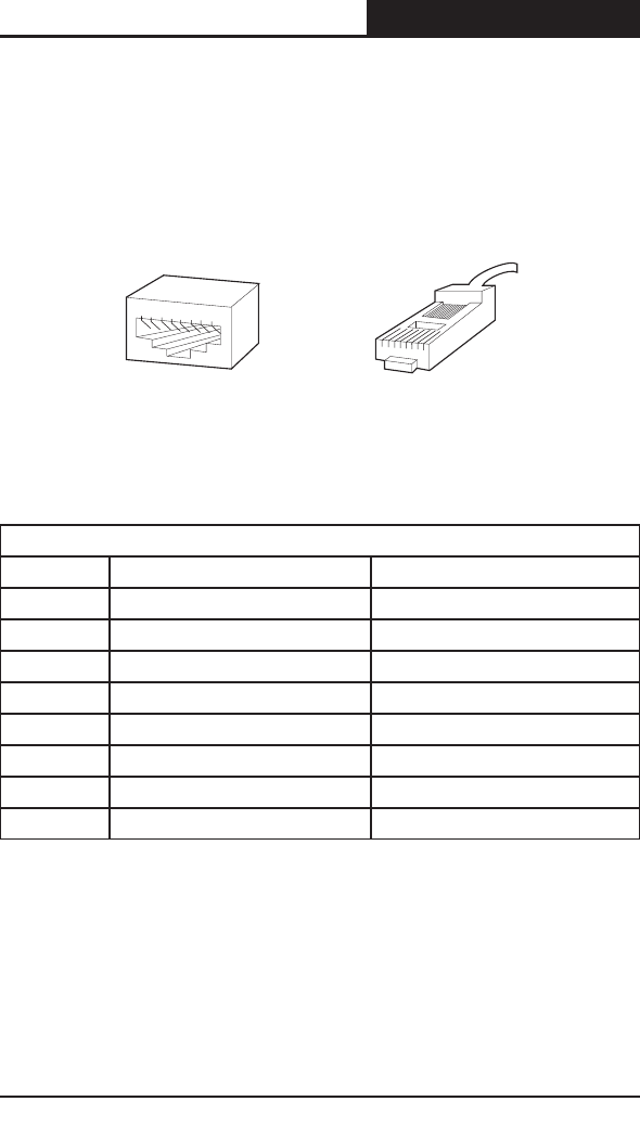
Appendix A Pin Explain For RJ-45 Connector
The switching port can connect to stations wired in standard RJ-45 Ethernet
station mode using straight cables. Transmission devices connected to each
other use crossed cables. The following gure illustrates the pin allocation:
8
7
6
5
4
3
2
1
1 2 3 4 5 6 7 8
Figure RJ-45 connector
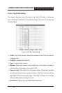
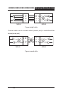
The following shows the way to make the cable use to connect switch to
network adapter, and cable use to connect switch to switch/hub/bridge.
Pin signal allocation for RJ-45 connector
Pin MDI-II MDI-X
1 TX+ (send) RX+ (receive)
2 TX- (send) RX- (receive)
3 RX+ (receive) TX+ (send)
4 No use No use
5 No use No use
6 RX- (receive) TX- (send)
7 No use No use
8 No use No use
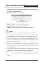
Straight cable: use to connect switch (uplink port) or network adapter to switch/
hub/other device (normal port).