


T
T
T
S
S
S
3
3
3
2
2
2
M
M
M
~
~
~
1
1
1
G
G
G
C
C
C
F
F
F
8
8
8
0
0
0
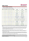
80X CompactFlash Card
Transcend Information Inc.
42
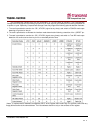
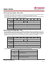
It is Bit 27 in the Logical Block Address mode.
Bit 2 (HS2)
: when operating in the Cylinder, Head, Sector mode, this is bit 2 of the head number.
It is Bit 26 in the Logical Block Address mode.
Bit 1 (HS1)
: when operating in the Cylinder, Head, Sector mode, this is bit 1 of the head number.
It is Bit 25 in the Logical Block Address mode.
Bit 0 (HS0)
: when operating in the Cylinder, Head, Sector mode, this is bit 0 of the head number.
It is Bit 24 in the Logical Block Address mode.
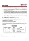
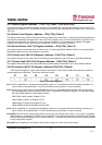
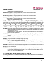
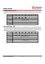
5.5.9 Status & Alternate Status Registers (Address 1F7h[177h]&3F6h[376h]; Offsets 7 & Eh)
These registers return the CompactFlash Storage Card status when read by the host. Reading the Status register does
clear a pending interrupt while reading the Auxiliary Status register does not. The status bits are described as follows:
Figure: Status & Alternate Status Register
Bit 7 (BUSY)
: the busy bit is set when the CompactFlash Storage Card has access to the command buffer and registers
and the host is locked out from accessing the command register and buffer. No other bits in this register are
valid when this bit is set to a 1.
During the data transfer of DMA commands, the Card shall not assert DMARQ unless either the BUSY bit,
the DRQ bit, or both are set to one.
Bit 6 (RDY)
: RDY indicates whether the device is capable of performing CompactFlash Storage Card operations. This bit
is cleared at power up and remains cleared until the CompactFlash Storage Card is ready to accept a
command.
Bit 5 (DWF)
: This bit, if set, indicates a write fault has occurred.
Bit 4 (DSC): This bit is set when the CompactFlash Storage Card is ready.
Bit 3 (DRQ): The Data Request is set when the CompactFlash Storage Card requires that information be transferred
either to or from the host through the Data register.
During the data transfer of DMA commands, the Card shall not assert DMARQ unless either the BUSY bit,
the DRQ bit, or both are set to one.
Bit 2 (CORR): This bit is set when a Correctable data error has been encountered and the data has been corrected. This
condition does not terminate a multi-sector read operation.
Bit 1 (IDX)
: This bit is always set to 0.
Bit 0 (ERR)
: This bit is set when the previous command has ended in some type of error. The bits in the Error register
contain additional information describing the error. It is recommended that media access commands (such
as Read Sectors and Write Sectors) that end with an error condition should have the address of the first
sector in error in the command block registers.
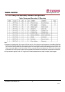
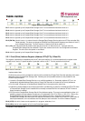
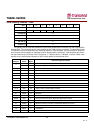
5.5.10 Device Control Register (Address - 3F6h[376h]; Offset Eh)
This register is used to control the CompactFlash Storage Card interrupt request and to issue an ATA soft reset to the
card. This register can be written even if the device is BUSY. The bits are defined as follows: