


12 HARDWARE INSTALLATION
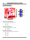
2.4 Connector Description
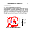
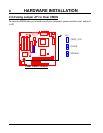
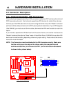
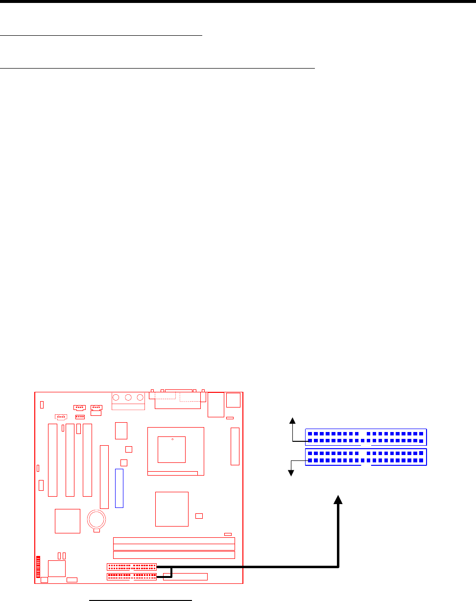
2.4.1 Primary/Secondary IDE Connectors
This motherboard supports two 40-pin IDE connectors marked as IDE1 (primary channel) and
IDE2 (secondary channel). Each channel supports two IDE devices for a total of four devices.
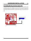
Connect your Hard Disk (the main one if you are using more than one) to the “Master” connector
(at the end of the cable) and connect it to IDE1 (see important note below). If your HDD supports
Ultra DMA/66, you must use an 80-wire cable, otherwise the HDD won’t be able to reach this
speed.
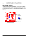
If you intend to operate two IDE devices from the same channel, one device must be set to
“Master” mode and the other to “Slave” mode. A Hard Disk Drive, CD ROM Drive or other IDE
device can have either setting, depending on device’s jumper setting. Please refer to the device’s
manual for more information.
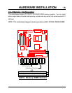
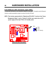
NOTE: The Connectors must be attached to the IDE channels correctly. Make sure
that the red stripe on the edge of the ribbon cable (this may be faint and
could be a dotted line) is the nearest to PIN 1 (on the left as the motherboard
is shown in the picture below).
IDE Connectors
PIN1
PIN1
Secondary IDE Connector
Primary IDE Connector
IDE2
IDE1
IDE
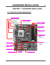
DIMM1
(
64bit 168pin SDRAM Module
)
DIMM2
(
64bit 168pin SDRAM Module
)
PCI Slot1 (PCI1)
PCI Slot2 (PCI2)
PCI Slot3 (PCI3)
CPU-FAN
WOL
FDC
IDE2
IDE1
GMCH
COMB
AC97
IntelICH
66/100MHz
Pin1
COMA
VGA
Parallel Port
Game Port
Line
_
in
MIC
Line
_
out
Li Batter
y
Transcend