


IONPS-A, AC Power Module
8
Tech Support: 1-800-260-1312 – International: 00-1-952-941-7600 – (24 hours)
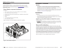
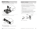
Figure 5: Power Module Installation
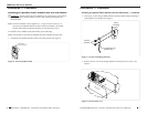
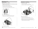
Figure 6: Power Module Installation
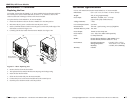
Note: Once the optional Power Module is seated to the backplane of the chassis,
the fans will become operational.
4. Position the Power Module at the chassis slot, as shown in Figure 5.
5. Side the Power Module completely into the chassis. See Figure 6.
Mounting Screws
Chassis
Power Module
Chassis
Installed Optional
Power Module
Installation — Continued
Installing an optional Power Module into the ION chassis — continued
Connecting the Power Module to external power
To connect external power to the IONPS-A, AC Power Module, do the following:
1. Locate the power cord for the Power Module.
2. Make sure that the Power Module ON/OFF switch is in the OFF position. See
Figure 7.
3. Plug the female end of the AC power cord into the AC power receptacle on the
Power Module. See Figure 7.
4. Plug the male end of the AC power cord into the AC power source.
5. Turn the power ON/OFF switch to the ON position. See Figure 7.
Note: Once the power ON/OFF switch is in the ON position, the power ON LED
will lite. This means that the optional Power Module is ready to power the
chassis if the primary Power Module fails.
Important: There is NO power sharing between the two Power Modules.
techsupport@transition.com – Click the “Transition Now” link for a live Web chat.
9
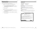
Figure 7: AC Power Cord Ends
6. Insert the two screws to mount the Power Module to the chassis.
Installation — Continued
Installing an optional Power Module into the ION chassis — continued
AC Power Cord
(female end)
Power Module
Power Cord
Receptacle
AC Power Cord
(male end)
Power Module
ON/OFF Switch