


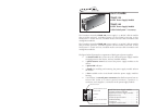

CPSMP-130 & CPSMP-140
4
24-hour Technical Support: 1-800-260-1312 -- International: 00-1-952-941-7600
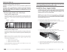
Connect to External Power
CAUTION: Ensure that external power source is NOT powered and that the
On/Off switch on the power supply module is set to “0” when connecting to
the external power source. Failure to observe this caution could result in
damage to, and subsequent failure of, the power supply module.
48-VDC power supply
• This product is intended to be used in a restricted access location. Proper
earthing (grounding) is required to ensure safe operation and to comply
with customer installation requirements and local electrical codes. Prior
to installation, use a voltmeter/ohmmeter to check the wiring for the
presence of earth ground.
• A readily accessible disconnect device as part of the building installation
shall be incorporated into the fixed wiring. The disconnect device (a 48
VDC, 15 or 20A circuit breaker or switch) must be included in the
ungrounded supply conductor. Overcurrent protection must be a 48
VDC, 15 or 20A fuse or circuit breaker.
24-VDC Power Supply
• This product is intended to be used in a restricted access location. Proper
earthing (grounding) is required to ensure safe operation and to comply
with customer installation requirements and local electrical codes. Prior
to installation, use a voltmeter/ohmmeter to check the wiring for the
presence of earth ground.
• A readily accessible disconnect device as part of the building installation
shall be incorporated into the fixed wiring. The disconnect device (a 24
VDC, 15 or 20A circuit breaker or switch) must be included in the
ungrounded supply conductor. Overcurrent protection must be a 24
VDC, 15 or 20A fuse or circuit breaker.
5
techsupport@transition.com -- Click the “Transition Now” link for a live Web chat.
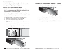
Connect to External Power -- Continued
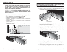
To power the CPSMP-130 or the CPSMP-140 power supply module:
1. Set the On/Off switch on the power supply module to “0”.
2. Verify that the external power source is NOT powered.
3. Connect the positive (+) terminal to the external power connector marked
“+”. Turn the terminal screw clockwise to secure.
4. Connect the negative (-) terminal to the external power connector marked
“-”. Turn the terminal screw clockwise to secure.
5. Connect the ground terminal to the external power connector marked
“chassis ground”. Turn the terminal screw clockwise to secure.
6. Set the power supply module power switch to “I”.
7. Verify that the power supply module is powered by observing the
illuminated power LED.
I
0
-
+
I
0
-
+
+
GND
–
Power LED
External Power Connectors
On/Off
Switch
Panel Fastener Screw