


CPSMP-130 & CPSMP-140
8
24-hour Technical Support: 1-800-260-1312 -- International: 00-1-952-941-7600
Replace the Fuse
CAUTION: Ensure that the power supply module has been disconnected
from the external power source and the module’s On/Off switch has been
set to “0”. Failure to observe this caution could result in damage to, and
subsequent failure of, the power supply module.
NOTE: The power supply module may be “hot swapped” (i.e., serviced while
the chassis is in operation) provided the module to be serviced has been
disconnected from its external power supply and the module’s On/Off
switch has been set to “0”.
To replace the fuse in the CPSMP-130 or CPSMP-140 power supply module:
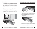
1. Set the On/Off switch on the power supply module to “0”.
2. Verify that the external power source is NOT powered.
3. Disconnect the positive (+) DC terminal from the external power
connector marked “+”.
4. Disconnect the negative (-) DC terminal from the external power
connector marked “-”.
5. Disconnect the ground terminal from the external power connector
marked “chassis ground”.
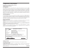
6. Rotate the attached panel fastener screw counter-clockwise.
7. Carefully slide the power supply module out of the chassis.
I
0
-
+
I
0
-
+
+
GND
–
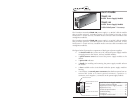
Power LED
External Power Connectors
On/Off
Switch
Panel Fastener Screw
I
0
-
+
I
0
-
+
9
techsupport@transition.com -- Click the “Transition Now” link for a live Web chat.
WARNING: Do NOT connect the power supply module to the external power
source before installing it into the chassis. Failure to observe this caution could
result in equipment damage and/or personal injury or death.
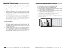
8. Remove the four (4) screws that secure the panel to the module (see the
drawing below) and remove the panel from module.
9. The fuse is located inside the power supply module on the circuit board.
Remove the fuse from the fuse holder.
10. Install a same size and rating replacement fuse in the fuse holder.
11. Replace the panel to the power supply module and secure it in place
with the four (4) screws.
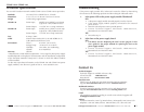
12. Carefully slide the power supply module into the installation slot,
aligning the module with the installation guides.
13. Ensure that the power supply module is firmly seated inside the chassis.
14. Rotate the attached panel fastener screw clockwise to secure the power
supply module to the chassis.
15. See the “Connect to External Power” section (page 5) for instructions on
re-connecting the power supply module to the external power source.
I
0
-
+
I
0
-
+
10BASE-2
I
0
-
+
+
+
+
+
Remove these four (4) screws
to access the fuse
I
0
Fuse location