


2
SCSCF30xx-10x
24-hour Technical Support: 1-800-260-1312 -- International: 00-1-952-941-7600
Part Number Port One - Copper Port Two - Single Fiber Optic
SCSCF3029-102 and -103 are intended to be installed in the same network where
one is the local converter and the other is the remote converter.
*Typical maximum cable distance. Actual distance is dependent upon the physical
characteristics of the network: (TX) = transmit, (RX) = receive.
SCSCF3029-102 75 ohm coax (BNC) SC, 1310 mn (TX)/1550 nm (RX)
40 km (24.8 miles)*
SCSCF3039-100 75 ohm coax (BNC) LC, 1300 mn multimode
2 km (1.2 miles)*
SCSCF3029-103 75 ohm coax (BNC) SC, 1550 mn (TX)/1310 nm (RX)
40 km (24.8 miles)*
Optional Accessories (sold separately)
Part Number Description
SPS-1872-SA Optional External Power Supply; 18-72VDC Stand-Alone
Output: 12.6VDC, 1.0 A
SPS-1872-PS Optional External Power Supply; 18-72VDC Piggy-back;
Output: 12.6VDC, 1.0 A
E-MCR-04 12-Slot Device Rack (includes universal internal power supply) 17 x
15 x 5 in. (432 x 381 x 127 mm)
WMBL Optional Wall Mount Brackets; 4.0 in. (102 mm)
WMBV Optional Vertical Mount Bracket; 5.0 in. (127 mm)
WMBD Optional DIN Rail Mount Bracket; 5.0 in. (127 mm)
WMBD-F Optional DIN Rail Mount Bracket (flat); 3.3in. (84 mm)
Installation
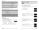
Set the Loop-Back Switch
The loop-back switch is located on the front panel of the Device and is used for
installation and network debugging procedures.
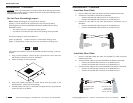
To set the switch, use a small flatblade screwdriver or a
similar device (see the drawing to the right).
CL (Coax loop-back) Enable loop-back on the local coax interface.
-- (Center Position) Normal operation.
FL (Fiber loop-back) Enable loop-back on the local fiber interface.
Note: Three loop-back test scenarios are described in detail on page 10.
CL FL
techsupport@transition.com -- Click the “Transition Now” link for a live Web chat.
3
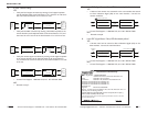
Switch 2 -- Coax Line Build Out (DS3 only)
up - The DS3 line is set up to operate at distances up to 225
ft. (68.6 m).
down - The DS3 line is set up to operate at distances greater
than 225 ft. (68.6 m).
<225 ft (68.6 m)
>225 ft (68.6 m)
down
up
Installation -- Continued
CAUTION: Wear a grounding device and observe electrostatic discharge
precautions when setting the configuration switches. Failure to observe this caution
could result in damage to, and subsequent failure of, the Device.
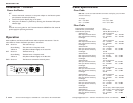
Set the Configuration Switches
The configuration switches are located on the side of the Device. Use a small, flat-
blade screwdriver to set the recessed switches.
Switch 1 -- Select DS3 or E3
up - Supports a DS3 interface.
down - Supports a E3 interface.
DS3
E3
down
up
Switch 3 -- Signal on Loss of Carrier
up - Transmits an alarm indication signal (AIS) on the loss of
the input carrier (unframed).
down - No signal is transmitted on the loss of the input
carrier (unframed).
Transmit alarm
No signal
up
down
Switch 4 -- Alarm Indication Signal (AIS)
up - AIS is defined as a pattern of alternating 1’s and 0’s
(unframed).
down - AIS is defined as a pattern of all 1’s (unframed).
A
larms = 1's and 0'
Alarm = all 1's
up
down