


6
SIBTF10xx-1xx-Mx
24-Hour Technical Support: 1-800-260-1312 International: 00-1-952-941-7600
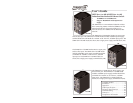
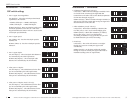
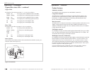
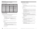
Figure 3: SIBTF10xx-110-MR Front Panel
Installation -- continued
Features -- continued
• The SIBTF10xx-110-MS industrial switch includes one (1) RJ-45, twisted-pair
copper port and one (1) 100 Mb fiber optic port.
• The Auto-Negotiation feature on port “1” can be turned OFF and forced to a
selected speed (100 Mb/s or 10 Mb/s) and duplex mode (full or half).
• All SIBTF models include a primary input terminal block (TB) for 48–170VDC or
90–125VAC power, a 2.5A, 250V fuse, an LED power indicator, and a fault LED.
The red-fault LED “ON state” indicates the microcontroller did not initialize
correctly.
• The “MR” models include an auxiliary power-supply terminal block—not available
on “MS” models.
See Figure 3.
techsupport@transition.com -- Click the “Transition Now” link for a live Web chat.
7
Installation -- continued
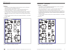
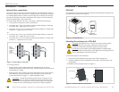
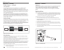
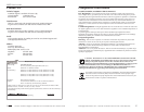
Enclosure top view (configuration switches)
The SIBTF10xx-1xx-Mx has eight (8) configuration (DIP) switches located under the
switch cover on top of the enclosure. See Figure 4.
Switch Position 1
1-Config Switches
Figure 4: Enclosure Top View Configuration Switches
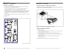
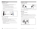
Setting configuration switches
To set the DIP switches:
1. Using a small, phillips-head screwdriver, loosen (do not remove) the two screws
that secure the cover to the switch.
2. Swing the switch cover counter-clockwise to expose the DIP switches.
3. Use a small, flathead screwdriver to set the recessed switches as required by the
network application.*
4. Slide the switch cover back over the DIP switches and then secure it by
tightening both screws.
*Note: Switches 1, 2, and 3 apply only to twisted-pair “copper port #1.”