


10
SIBTF10xx-1xx-Mx
24-Hour Technical Support: 1-800-260-1312 International: 00-1-952-941-7600
Installation -- continued
Note: DO NOT use bare (exposed) or un-lugged power-source wires to connect to the
industrial switch.
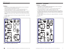
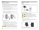
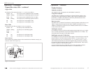
Connecting primary power
The industrial switch is designed to accommodate 48 – 170VDC or 90 – 125VAC,
50/60 Hz input power via its primary terminal block (TB).
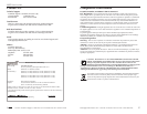
To provide power to the industrial switch via the primary TB, view Figure 5, and then
do the following:
1. Verify that the external power source is turned OFF and disconnect.
2. Loosen the grounding screw and then connect the power source functional-ground
lead to the grown screw, as shown in Figure 5. Tighten the screw to secure.
3. Loosen the TB screw marked “-” and then connect the power source neutral or (-)
negative lead to the TB negative terminal, as shown in Figure 5. Tighten the
screw to secure.
4. Loosen the TB screw marked “+” and then connect the power source line phase or
positive (+) lead to the TB positive terminal, as shown in Figure 5. Tighten the
screw to secure.
5. Re-connect and turn ON the external power source.
6. Verify that the industrial switch has powered up by observing the illuminated
“Power Good” LED on the front panel.
N
L
PRI.
48 - 170 VDC
90 - 125 VAC
POWER INPUT
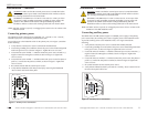
WARNING: Make sure that the external power source is turned OFF before
attempting to connect power leads to the industrial switch. Failure to observe
this warning could result in an electrical shock.
Figure 5: Primary Power Connection
WARNING: The SIBTF10xx-1xx-Mx is a class I device. It has a provision
for protective earth grounding. Equipment grounding is vital to ensure safe
operation. The SIBTF switch must be earth grounded during and after
installation. Failure to observe this warning could result in an electric shock.
techsupport@transition.com -- Click the “Transition Now” link for a live Web chat.
11
Installation -- continued
Note: DO NOT use bare (exposed) or un-lugged power-source wires to connect to the
SIBTF10xx-10x-MR industrial switch.
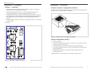
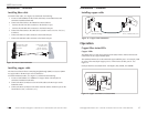
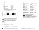
Connecting auxiliary power
The SIBTF10xx-10x-MR switches support a redundant power supply. If the primary
power source fails, the auxiliary power source supplies power to the industrial switch.
To provide auxiliary power to the industrial switch, view Figure 6 and do the
following:
1. Verify that the external power source is turned OFF and disconnected.
2. Loosen the grounding screw and connect the power source functional-ground lead
to the grown screw, as shown in Figure 6. Tighten the screw to secure.
3. Loosen the TB screw marked “-” and then connect the power source neutral or (-)
negative lead to the TB negative terminal, as shown in Figure 6. Tighten the
screw to secure.
4. Loosen the TB screw marked “+” and then connect the power source line phase or
positive (+) lead to the TB positive terminal, as shown in Figure 6. Tighten the
screw to secure.
5. Re-connect and turn ON the external power source.
6. Verify that the industrial switch is powered UP: auxiliary “Power Good” LED on
the lower front panel will be ON.
AUX.
Figure 6: Auxiliary Power Connection
WARNING: Make sure that the external power source is turned OFF before
attempting to connect power leads to the industrial switch. Failure to observe
this warning could result in an electrical shock.
WARNING: The SIBTF10xx-1xx-Mx is a class I device. It has a provision
for protective earth grounding. Equipment grounding is vital to ensure safe
operation. The SIBTF switch must be earth grounded during and after
installation. Failure to observe this warning could result in an electric shock.