


Installation -- continued
Internal relay connections
The internal relay can activate an external fault indicator. The fault indicator connects
to the relay contacts on the front panel. An example would be a fault circuit connected
to a warning light located in a control room. The light can be connected in a normally
open (NO) or normally closed (NC) configuration with respect to circuit common (C)
to turn the light ON/OFF when a fault occurs.
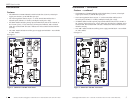
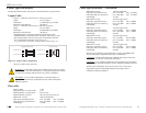
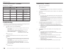
To connect a fault indicator to the relay, view Figure 7 and then do the following:
1. Verify that the external power source is turned OFF.
2. Loosen the relay’s “NO” screw and then connect the fault indicator’s return lead
to terminal “NO.” Tighten the screw to secure.
3. Loosen the relay’s “C” screw and then connect the fault indicator’s common lead
terminal “C.” Tighten the screw to secure.
Or:
4. Loosen the relay’s “NC” screw and then connect the fault indicator’s return lead
to terminal “NC.” Tighten the screw to secure.
5. Loosen the relay’s “C” screw and then connect the fault indicator’s common lead
terminal “C.” Tighten the screw to secure.
Two wiring scenarios:
• Wiring the relay in the normally closed (NC) configuration can be used to
monitor alarm indicators connected in series, where any single event will cause all
alarm indicators to trigger.
• Wiring the relay in the normally open (NO) configuration can be used to monitor
alarm indicators connected in parallel, where any single event will cause that
events alarm indicator to trigger: i.e., a light turning ON or OFF.
12
SIBTF10xx-1xx-Mx
24-Hour Technical Support: 1-800-260-1312 International: 00-1-952-941-7600
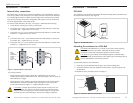
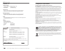
NC
C
NO
NC
C
NO
Relay
Contacts
(600W max.)
30 VDC
@2.0A
125 VAC
@0.5A
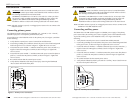
CAUTION: Calculate the maximum possible current in each power wire
and relay-contact wire. Observe all electrical codes for maximum current
allowed. If the current goes above the maximum ratings, the wiring could
overheat and cause serious damage to the network wiring or equipment.
Figure 7: Internal Relay Connections
techsupport@transition.com -- Click the “Transition Now” link for a live Web chat.
13
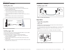
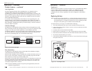
Mounting the enclosure to a DIN-Rail
To mount the enclosure onto a DIN-Rail:
1. Insert the top of the DIN-Rail into the upper slot of the mounting plate.
2. Push down and then rotate the industrial switch inward to snap it into place onto
the DIN-Rail.
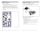
An illustration of the procedure is shown in Figure 9.
Step 1 Step 2
Mounting Plate
DIN-Rail
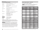
Installation -- continued
DIN-Rail
The industrial switch includes an aluminum DIN-Rail mounting bracket attached to the
back panel of the enclosure. See Figure 8.
DIN Rail
Mounting Bracket
Back View
Figure 8: DIN-Rail Bracket
Figure 9: Enclosure Mounted to DIN-Rail
CAUTION: The SIBTF10xx-1xx switch is convection cooled, requiring
unrestricted bottom-to-top airflow. Mounting the device in other
orientations could result in unreliable operation or device failure.
CAUTION: To prevent debris from falling through the ventilation holes,
local and national electrical and fire codes might require orienting the device
with its small-diameter vent holes downward.