


10
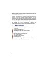
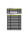
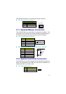
Connector Definition Page
PC1 / PC2 PC/104 Bus 64-pin/40-pin Connectors 22
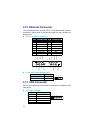
USB1 External USB Connector 15
USB2/USB3 Internal USB Connectors 15
RT1/RT2 Power Sensing Connectors 18
VGA1
15-pin VGA Connector 10
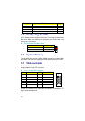
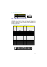
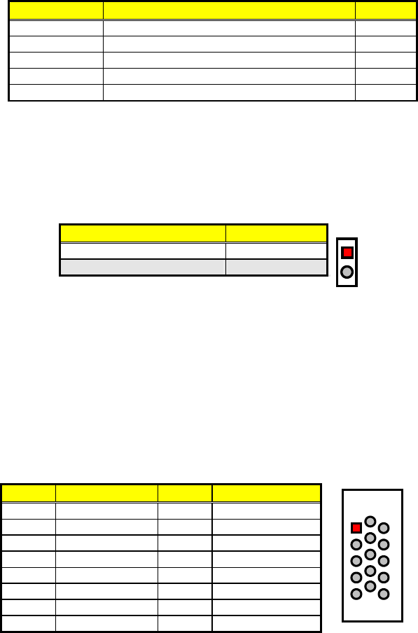
3.5 Configuring the CPU
JP2 is used to set the Host Bus Clock Rate. The setting of internal Host
Bus Clock Rate is for defining the operating clock base rate of the
internal bus of core logic.
JP2: Host Bus Clock Rate Select
Description Setting
66/100MHz FSB Short
133MHz FSB (default) Open
1
2
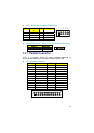
3.6 System Memory
The HS-6038 provides two 168-pin DIMM sockets at locations DIM1
and DIM2. The maximum capacity of the onboard memory is 512MB.
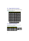
3.7 VGA Controller
The HS-6038 provides one connection for VGA device. VGA1 offers a
single standard 15-pin CRT connector.
VGA1: 15-pin CRT Connector
PIN Description PIN Description
1 Red 2 Green
3 Blue 4 VCC
5 GND 6 GND
7 GND 8 GND
9 VCC 10 GND
11 VCC 12 DDCDA
13 HSYNC 14 VSYNC
15 DDCCL
1
6
10
11
5
15
An Inter-IC connector CN9, also offers the flexibility of installing an I
2
C
digital signal-based device.