18
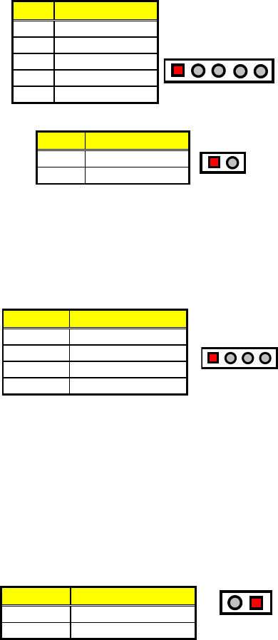
CN1 and CN7 are the Keylock and Reset Button connectors onboard.
CN1: Keylock Connector
PIN Description
1 VCC
2 N/C
3 GND
4 Keylock
5
GND
12345
CN7: 2-pin Reset Button Connector
PIN Description
1 GND
2 H/W Reset
12
3.19 External Speaker
Aside from the buzzer at location BZ1 onboard, the HS-6038 also
offers a connector (CN2) for an external speaker connection. The table
below lists the pin assignments of CN2.
CN2: Speaker Connector
PIN Description
1 Speaker Signal
2 GND
3 GND
4 +5V
1234
3.20 Thermal Input Connectors
In relevance to the Hardware Monitoring feature provided by the
onboard Winbond W83627, the board allows the installation of a
thermal sensor via connectors RT1/RT2 and JP1. The thermal
connector JP1 monitors and displays the current system temperature
whereas RT2 monitors the temperature conditions along the area
where the power supply system sits. The displayed values are
read-only figures and may not be altered.
RT1, RT2, JP1: System/Power Sensing Connectors
PIN Description
1 Sensing
2 GND
12


