


7
Basic Operation
(continued)
6
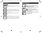
Front Panel Indicator Lights
continued
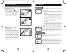
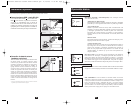
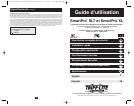
“BOOSTING” LED: This yellow light will be lit when the UPS is
boosting AC utility power to nominal levels and providing it to connected
equipment. The UPS will click faintly when boosting AC power. This
is a normal, automatic function of your UPS and no action is required
on your part. If your UPS has to boost power frequently, you may be
in a poor power area, and should consider obtaining power protection
for equipment that is not connected to a UPS.
“ON BATTERY” LED: This yellow light will be lit when your UPS
is providing your equipment with battery power. The UPS will also
beep every two seconds, unless silenced by the “ON/TEST” Switch.
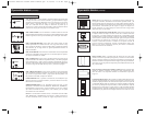
“BATTERY METER” LEDs: These four green lights show the
approximate charge remaining in the UPS battery. If the battery
charge is very low, the 25% LED will flash and the UPS alarm will
beep every second to warn you that the remaining charge will be
depleted quickly by connected equipment.
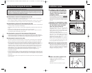
“LOAD METER” LED: These four green lights show approximate-
ly how much of the UPS’s power capacity is used to support the equip-
ment connected to the outlets.
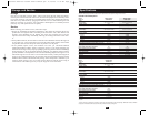
“OVERLOAD” LED: This red light will be lit when the power draw
of equipment connected to the Battery, Surge and Noise Protected
outlets exceeds your UPS’s power capacity. The UPS alarm will beep
continuously. Immediately disconnect excess equipment from the
outlets until the light and alarm turn off.
“CHECK BATTERY” LED: This red light will be lit if your UPS’s
microprocessor detects a battery fault or if the UPS battery is very
weakly charged. Let your UPS charge for 8 hours, then run another
self-test. If the light stays on, replace the batteries.
SHORT CIRCUIT: If a short circuit occurs, the UPS will stop providing
power to connected equipment and the alarm will sound. If this happens,
eliminate the short circuit.
OVERTEMPERATURE: If the temperature inside the UPS gets too
high, the NORMAL, BOOSTING, TRIMMING and ON BATTERY
LEDs will all light at once and the alarm will sound. If this happens,
check to make sure the UPS’s ventilation grills are unobstructed and
that it is located in a cool, well-ventilated area.
FAULT: If the UPS detects an internal failure, its NORMAL,
BOOSTING and TRIMMING LEDs will light and its alarm will
sound. If this happens, disconnect the UPS and contact Tripp Lite for
service.
NORMAL
BOOSTING
OVERLOAD
METER
100%
75%
50%
25%
80%
60%
40%
20%
BATTERY
METER
LOAD
OVERLOAD
80%
Basic Operation
(continued)
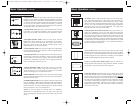
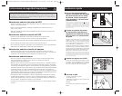
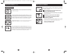
Rear Panel
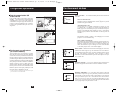
AC Outlets: These 15-amp receptacles provide your connected equip-
ment with voltage regulated AC output from the AC line during nor-
mal operation and from battery power during power failures. These
outlets also protect connected equipment against power surges on the
AC line. Your UPS is designed to support only computer equipment
with battery power. Do not connect equipment with high power
demands (like laser printers) to these outlets.
Communications Ports (USB or RS-232): These ports connect your
UPS to any workstation or server. Use with Tripp Lite's PowerAlert
Software and included cables to enable your computer to automatically
save open files and shut down equipment during a blackout. Also use
PowerAlert Software to monitor a wide variety of AC line power and
UPS operating conditions. Consult your PowerAlert Software manual
or contact Tripp Lite Customer Support for more information. See “USB
and RS-232 Serial Communications” in the “Optional Installation”
section for installation instructions.
Accessory Slot: Remove the small cover panel from this slot to install
optional accessories to remotely monitor and control your UPS. Refer
to your accessory’s manual for installation instructions. Contact Tripp Lite
Customer Support for more information, including a list of available
SNMP, network management and connectivity products.
TVSS Cover Plate (Select Models Only): Remove this plate to
install optional modem/network surge protection modules, available
for purchase by special arrangement with Tripp Lite.
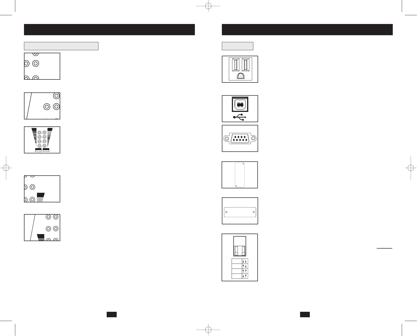
Voltage Dip Switch: Matches the UPS System’s output voltage to the
input voltage available at the wall outlet. See Quick Installation section
for setting instructions. Note: if the Voltage Dip Switch setting does
not
match your input voltage (if it is set above or below the input voltage),
the UPS system will naturally consider the input voltage as a constant
overvoltage or undervoltage condition. The UPS system will respond
accordingly by automatically adjusting the input voltage to match the
Voltage Dip Switch setting. This will cause constant, unnecessary
wear on the UPS system.
CC
ON
BATTERY
B
O
CHECK
BATTERY
ON
BATTERY
100%
TVSS
120V
110V
100V
127V
200308025 Smart1050-1500SLT Owner’s Manual.qxd 11/14/2003 11:40 AM Page 6