


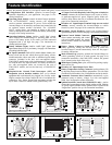
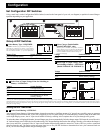
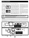

Ground*
• Connect the incoming and outgoing ground wires to the
GROUND (green) terminal .
AC Input
• Connect the incoming hot wire to the input hot
(brown) terminal .
• Connect the incoming neutral wire to the input neutral (blue)
terminal .
AC Output
• Connect the outgoing hot wire to the output hot
(black) terminal .
• Connect the outgoing neutral wire to the output neutral (white)
terminal .
Replace cover plate and tighten screws. * If the incoming conduit only contains two wires (hot
and neutral), the incoming conduit must be bonded to the main ground lug on the unit. In any
case, the incoming conduit must be bonded to earth or vehicle ground, and the incoming conduit
must be bonded to the outgoing conduit.
1
2
3
4
5
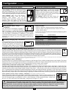
AC Input/Output Connection
To avoid overloading your Inverter/Charger, be sure to match the power requirements of the equipment you plan to run at any one time (add their
total watts) with the output wattage capacity of your Inverter/Charger model (see Specifications). When figuring the power requirements
of your equipment, do not confuse “continuous” wattage with “peak” wattage ratings. Most electric motors require extra power at start-up
(“peak wattage”) than required to run continuously after start-up, sometimes over 100% more. Some motors, such as in refrigerators and
pumps, start and stop intermittently according to demand, requiring “peak wattage” at multiple, unpredictable times during operation.
Connection for Models with Cords and Receptacles
Plug the Inverter/Charger’s AC input cord into an outlet providing 120V AC, 60Hz. power. Make sure that the circuit you connect your
Inverter/Charger to has adequate overload protection, such as a circuit breaker or a fuse. To make use of AC output (either utility/genera-
tor pass-through power or inverter power) simply plug your equipment into the Inverter/Charger's AC receptacles. Any equipment you con-
nect to it will benefit from your Inverter/Charger’s built-in ISOBAR
®
surge protection!
Warning! Consult a qualified electrician and follow all applicable electrical codes
and requirements for hardwire connection. Disconnect both DC input and AC utility
supply before attempting hardwiring. Use wire type THHN or equivalent with
minimum temperature rating of 90°C.
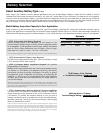
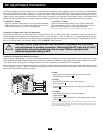
Connection for Models with Hardwire Terminals
Output Connection Requirement: UL requires that the output terminals of all hardwired Inverter/Charger models must be connected to UL-listed
GFCI receptacles (required receptacle manufacturer/model series: Hubbell GF8200HW or Leviton 8598 HGW copper wiring devices XHGF-
15W). When wiring GFCI receptacles to output terminals, follow the instructions provided with the GFCI receptacles.
Remove the screws and cover plate over the hardwire terminal box. Remove the knockout covers closest to the desired electrical source and
to your equipment. Attach ½" diameter conduits (user-supplied) to the knockouts and thread wires through. Connect the conduits to each
other with the ground bond connection supplied.
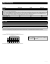
HOT IN
NEUTRAL IN
GROUND IN
GROUND OUT
HOT OUT
“FOR USE WITH COPPER WIRE ONLY”
NEUTRAL OUT
2
3
1
4
5
Note: Ground Bond Connection Supplied
10E
• DoubleBoost
™
Feature
Tripp Lite Inverter/Chargers deliver up to twice their nameplate
rated wattage for up to 10 seconds,* providing the extra power
needed to cold start heavy-duty tools and equipment.
• OverPower
™
Feature
Tripp Lite Inverter/Chargers deliver up to 150% of their name-
plate rated wattage for up to 1 hour,* providing plenty of reserve
power to reliably support tools and equipment longer.
* Actual duration depends on battery age, battery charge level and ambient temperature.