


6E
Configuration
(Continued)
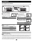
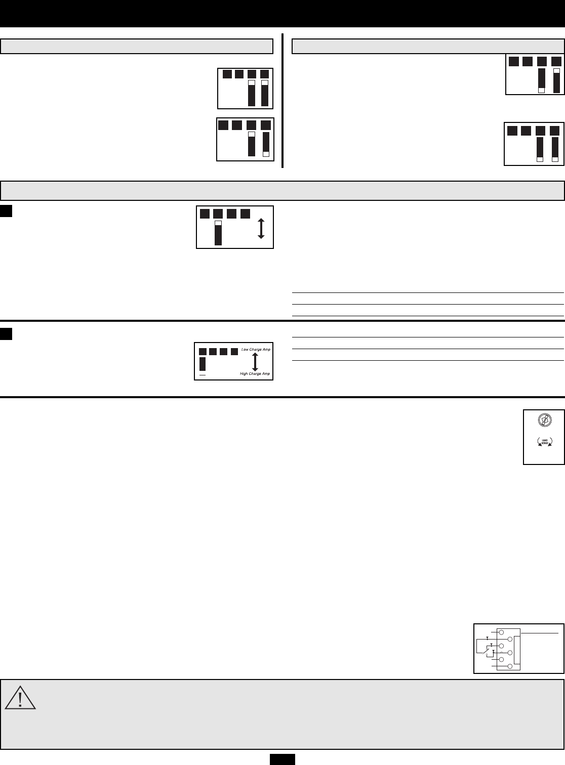
Set Battery Charging Amps—OPTIONAL
Check specifications for your unit’s high- and
low-charging amp options. By setting on high
charging, your batteries will charge at maxi-
mum speed. When setting on low charging,
you lengthen the life of your batteries (especially smaller ones).
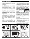
Battery Charger Switch Position
Low Charge Amp Up (EMS1012UL & EMS2012ULfactory setting)
High Charge Amp Down (EMS1250UL factory setting)
CAUTION: When switching to the High Charge Amp setting, the user must ensure that the amp
hour capacity of their battery system exceeds the amperage of the High Charge Amp setting or
the batteries may be damaged or degraded.
Select Equalize Battery Charge—
OPTIONAL
This DIP Switch is momentarily engaged to
begin the process of equalizing the charge
state of your battery’s cells by time-limited overcharge of all cells.
This can extend the useful life of certain types of batteries; consult
with your battery’s manufacturer to determine if your batteries
could benefit from this process. The charge equalization process is
automatic; once started, it can only be stopped by removing the
input power.
Setting Procedure
• Move to “Equalize” (DOWN) position for three seconds.
• Move to “Reset” (UP) position and leave it there. This is the
factory default setting.
CAUTION: Do not leave DIP switch #B3 in the down position after beginning process. Battery
charge equalization should only be performed in strict accordance with the battery manufacturer’s
instructions and specifications.
Battery Charge Switch Position
Reset Up (factory setting)
Equalize Down—momentarily
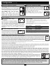
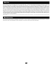
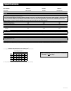
Select Battery Charger-Limiting Points—OPTIONAL
“Most Limiting” (#B2 & #B1 Up) Charger-limiting
takes effect the moment any 120V AC load is applied;
charger output falls gradually from full output at no
120V load passing through to no output at full load.
“Less Limiting” (#B2 UP & #B1 Down): :
Charger-limiting begins when the Inverter/
Charger’s load reaches 33% of the
Inverter/Charger’s load rating. Charger output falls
gradually from full output at 33% of the
Inverter/Charger’s load rating to about 40% of full output at full load.
“Least Limiting” (#B2 Down & #B1 Up):
Charger-limiting begins at when the Inverter/
Charger’s load reaches 66% of the Inverter/
Charger’s load rating. Charger output falls gradual-
ly from full output at 66% of the Inverter/Charger’s load rating to
about 40% of full output at full load.
“No Limiting” (#B2 & #B1 Down, factory set-
ting): No charger-limiting occurs at any load size.
B1B2B3B4
B1B2B3B4
B1B2B3B4
B1B2B3B4
B1B2B3B4
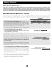
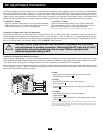
Set Battery Charge Conserver (Load Sense) Control—OPTIONAL
In order to save battery power, the unit’s inverter automatically shuts off in the absence of any power demand from connected equip-
ment (the electrical load). When the unit detects a load, it automatically turns its inverter function on. Users may choose the minimum
load the Inverter/Charger will detect by adjusting the Battery Charge Conserver Control (see diagram). Using a small tool, turn the con-
trol clockwise to lower the minimum load that will be detected, causing the inverter to turn on for smaller loads. When the control is
turned fully clockwise, the inverter will operate even when there is no load. Turn the control counterclockwise to increase the minimum
load that will be detected, causing the inverter to stay off until the new minimum load is reached.
Note: the factory setting for the control is fully clockwise. However, based on the threshold load to which you’d like the inverter to respond, you should adjust the control counterclockwise to reduce its
sensitivity until the inverter is active only when connected equipment or appliances are actually in use.
Connect Remote Control—OPTIONAL
All models feature an 8-conductor telephone style receptacle on the front panel for use with the included remote control module. The remote
module allows the Inverter/Charger to be mounted in a compartment or cabinet out of sight, while operated conveniently from within the cab
or patient-care area of your EMS vehicle. See instructions packed with the remote control module.
Connect Battery Temperature Sensing Cable—OPTIONAL
(Not available on EMS1250UL models)
The battery temperature sensing function prolongs battery life by adjusting the charge level based on battery temperature. Connect the sensor
cable (the cable, included with select models, has an RJ style connector on one end and a black sensor on the other) to the RJ style jack
located on the side of the Inverter/Charger labeled “Remote Temp. Sense.” Affix the sensor to the side of your battery below the electrolyte
level. To guard against false readings due to ambient temperature, place the sensor between batteries, if possible, or away from sources of extreme
heat or cold. If the sensor cable is not used, the Inverter/Charger will charge according to its B4 Dip Switch setting. This function does not
replace the Battery Charge Amps DIPSwitch B4 setting. Charge amps will remain in the vicinity of the level you have set with the B4 DIPSwitch.
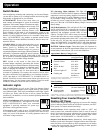
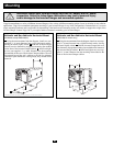
Utilize Automatic Generator Starter Capability—OPTIONAL (Not available on EMS1250UL models)
Select EMS models include an RJ type modular jack labeled “Generator Start.” Attach to vehicle generator on-off
switching mechanism with user-supplied cable (see Pin Configuration Diagram). Once attached, the interface will
allow the Inverter/Charger to automatically switch a vehicle generator on when connected battery voltage levels
are low (11.6 VDC) and switch it off when battery voltage levels are high (14.1 VDC).
Reset
Equaliz
e
B1B2B3B4
OFF
(LESSER
LOAD
ON)
MAX
(GREATER
LOAD
ON)
B4
B3
1
2
3
4
5
6
Pin Configuration
2 - Common
3 - N.C.
(Normally Closed)
4 - N.O.
(Normally Open)
EMS1012UL & EMS2012UL Models* EMS1012UL & EMS2012UL Models*
* Charger limiting function varies by model. On Models EMS1012ULand EMS2012UL, all settings are functional. On Model EMS1250UL, charger limiting is preset to “Most Limiting”;
switches are non-functional.
Ignition Interlock Control function (Model EMS1250UL only): This function automatically disables (turns OFF) AC power output from the invert-
er/charger when the vehicle’s ignition switch is placed in the “Engine Run” position. This function will satisfy local codes and requirements con-
cerning video monitors or TVs that are located within a driver’s view by automatically turning them off when the engine is started. Using the
included interface cable,* connect the black lead to vehicle ground (battery negative). Connect the red lead to the “Engine Run” terminal of the vehicle's
ignition switch. Then connect the interface cable's mini-plug to the Ignition Switch Control Jack on the unit (see p. 3 for location of jack).
* The interface cable has a mini-plug on one end and two wire leads (one black and one red) on the other.