


3E
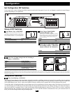
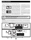
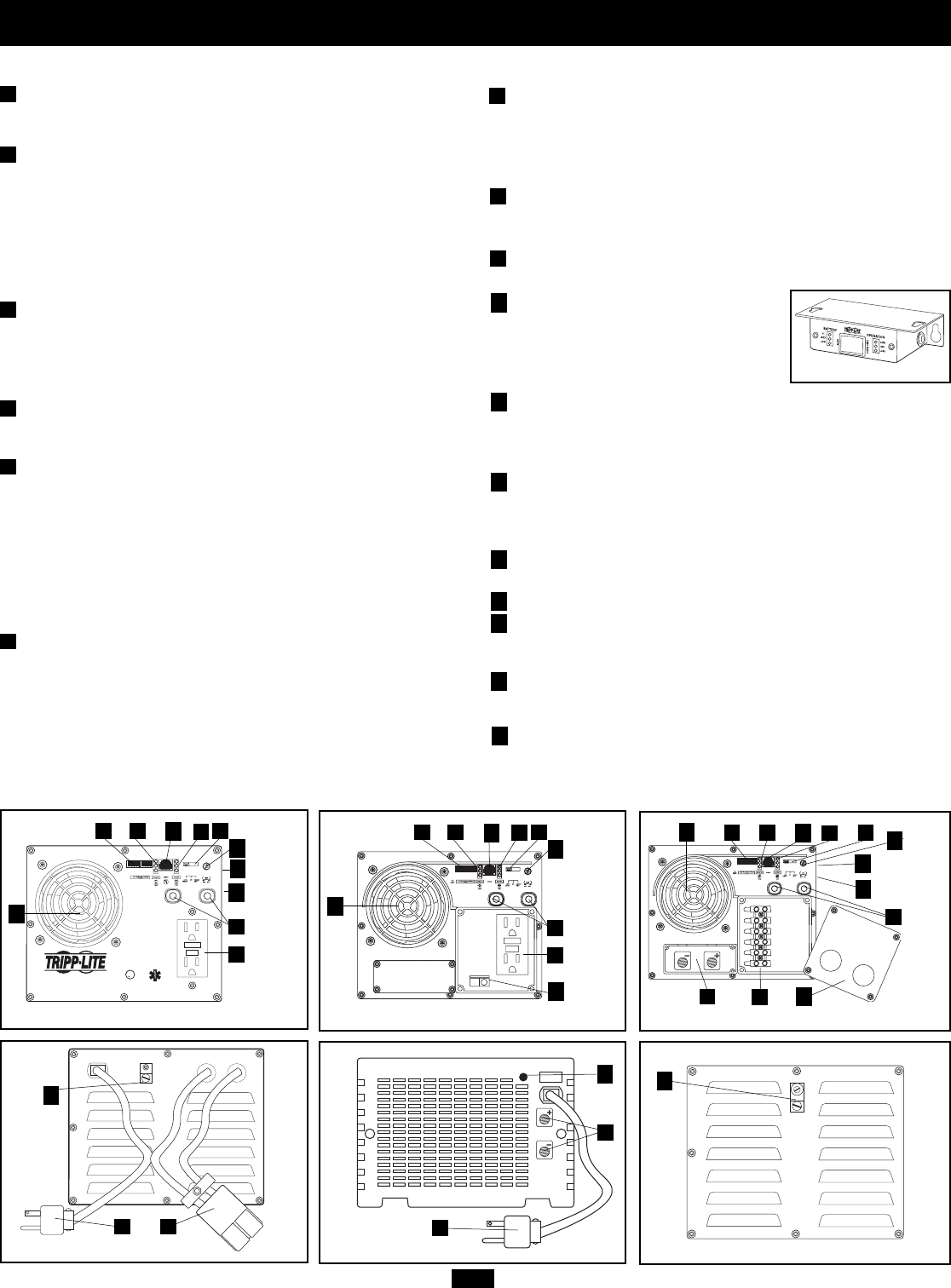
Feature Identification
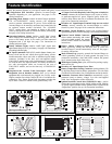
Configuration DIP Switches: optimize Inverter/Charger
operation depending on your application. See pages 5-6 for
setting instructions.
Operating Mode Switch: controls Inverter/Charger operation.
The “AUTO/REMOTE” setting ensures your equipment
receives constant, uninterrupted AC power. It also enables the
Inverter/Charger to be remotely monitored and controlled with
an optional remote module (included). The “CHARGE
ONLY” setting allows your batteries to return to full charge
faster by turning the inverter off which halts battery discharging.
See page 4 for setting instructions.
Operation Indicator Lights: intuitive “traffic light” signals
show whether the Inverter/Charger is operating from AC line
power or DC battery power. It also warns you if the connected
equipment load is too high. See page 4 for instructions on
reading indicator lights.
Battery Indicator Lights: intuitive “traffic light” signals show
approximate charge level of your battery. See page 4 for instructions
on reading indicator lights.
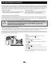
DC Input Connection: EMS1012UL models feature a battery con-
nector wired into the unit which allows quick battery connec-
tion/disconnection when used with an additional quick battery
connector (included in the box) and user-supplied cables.
EMS1250UL models come with a cable/connector assembly for
use with the unit's DC input terminals. DC battery terminals for
use with user-supplied cables are located on the rear of
EMS1250UL models, and on the front only of EMS2012UL
models.
Hospital-Grade Ground Fault Interrupter (GFI) AC
Receptacles (not on hardwire models): allow you to connect
equipment that would normally be plugged into a utility outlet.
Higher retention force helps reduce the risk of accidental dis-
connection. They feature ground fault interrupter switches that
trip if there is excessive current on the ground safety wire.
AC Input Cord with Hospital-Grade Plug (not on hardwire
models): connects the Inverter/Charger to any source of utility-
or generator-supplied AC power. Superior quality blade con-
struction helps reduce the risk of accidental disconnection. See
page 10 for connection instructions.
Hardwire AC Input/Output Terminal Strip (not on corded
models): securely connects the Inverter/Charger to vehicle
electrical system. See page 10 for connection instructions.
Resettable Circuit Breakers: protect your Inverter/Charger
against damage due to overload. See page 4 for resetting instructions.
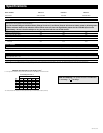
Remote Control Module Connector:
allows remote monitoring and control
with an included module. See remote
module owner’s manual for connection
instructions.
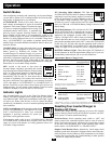
Battery Charge Conserver (Load Sense) Dial: conserves
battery power by setting the low-load level at which the
Inverter/Charger’s inverter automatically shuts off. See page 6
for setting instructions.
Main Ground Lug: properly grounds the Inverter/Charger to
vehicle grounding system or to earth ground. See page 9 for
connection instructions. (On EMS1250UL models, the ground
lug is located on the front of the unit.)
Multi-Speed Cooling Fan: quiet, efficient fan prolongs equip-
ment service life.
Hardwire AC Input/Output Cover Plate
Battery Temperature Sensing Connector: prolongs battery life
by adjusting charge based on battery temperature. Use with cable
(included on select models). See Configuration section for details.
Automatic Generator Start Connector: automatically cycles
generator based on battery voltage. Use with user-supplied
cable. See Configuration section for details.
Ignition Interlock Control Jack (EMS1250UL only) : used to
connect the inverter/charger to the vehicle ignition switch. Disables
AC power output when the vehicle ignition switch is placed in the
“Engine Run” position. See p. 6 for connection instructions.
Identify the premium features on your specific model and quickly locate instructions on how to maximize their use.
INPUT
BREAKER
OUTPUT
BREAKER
CUS
U
L
LISTED
POWER INVERTER
1DA8
1
2
3
4
5
6
7
8
9
10
Model: EMS1012UL Front View
Model: EMS1012UL Rear View
HOT IN
NEUTRAL IN
GROUND IN
GROUND OUT
HOT OUT
“FOR USE WITH COPPER WIRE ONLY”
NEUTRAL OUT
Model: EMS2012UL Front View
EMS Remote Control Module (included)
Model: EMS2012UL Rear View
Side Mounted,
Not Shown
Side Mounted,
Not Shown
Side Mounted,
Not Shown
11
12
13
14
15
16
13
1 4
10
3
2
11
15
16
9
6
12
57
12
13
1 4
10
3
2
11
15
16
9
14
5
8
Side Mounted,
Not Shown
Model: EMS1250UL Front View
Model: EMS1250UL Rear View
13
1 4
10
3
2
11
9
6
12
7
5
17
17