


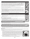
STEP 1: Install the UPS in either a horizontal (rackmount) or vertical (tower) configuration.
To install the UPS in a 4-post rack, attach the included mounting hardware to the UPS as shown in diagram . To mount the UPS in a
2-post rack, attach the included hardware to the UPS as shown in diagram . Then, using an assistant if necessary, lift the UPS and attach
it to a standard rack or rack enclosure with user-supplied hardware. Caution: If the UPS is installed in a rack, allow at least 0.75 in.
(2 cm) clearance above and below the unit. If the UPS is placed flat on a surface, do NOT stack any other object directly on top
of the unit. The UPS will stand in a tower position without the aid of the included hardware. However, for added stability Tripp Lite rec-
ommends that the included hardware be attached as shown in diagram . The UPS and included hardware are designed for common rack
and rack enclosure types and may not be appropriate for all applications.
STEP 2: Plug the UPS into an outlet that doesn’t share a circuit with a heavy electrical load.*
* An air conditioner, refrigerator, etc.
After plugging the UPS into a wall outlet, push the ON/OFF button for one second to turn the UPS on (see Basic Operation section).
Please Note! The UPS will not turn on automatically in the presence of live utility power.
STEP 3: Plug your equipment into the UPS.
* Your UPS is designed to support electronic equipment only. You will overload the UPS if the total VA ratings for all the equipment
you connect to the outlets exceeds the UPS’s Output Capacity. To find your equipment’s VA ratings, look on their nameplates. If the
equipment is listed in amps, multiply the number of amps by 120 to determine VA. (Example: 1 amp × 120 = 120 VA).
If you are unsure if you have overloaded the outlets, run a self-test (see “MUTE/TEST” Button description).
STEP4: Optional Installation. All models include USB and RS-232 communication ports as well as Tel/DSL/network and coaxial surge
protection jacks. These connections are optional; the UPS will work properly without these connections. See the connector’s description
in the Basic Operation section for connection instructions.
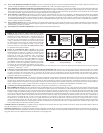
C
B
A
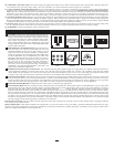
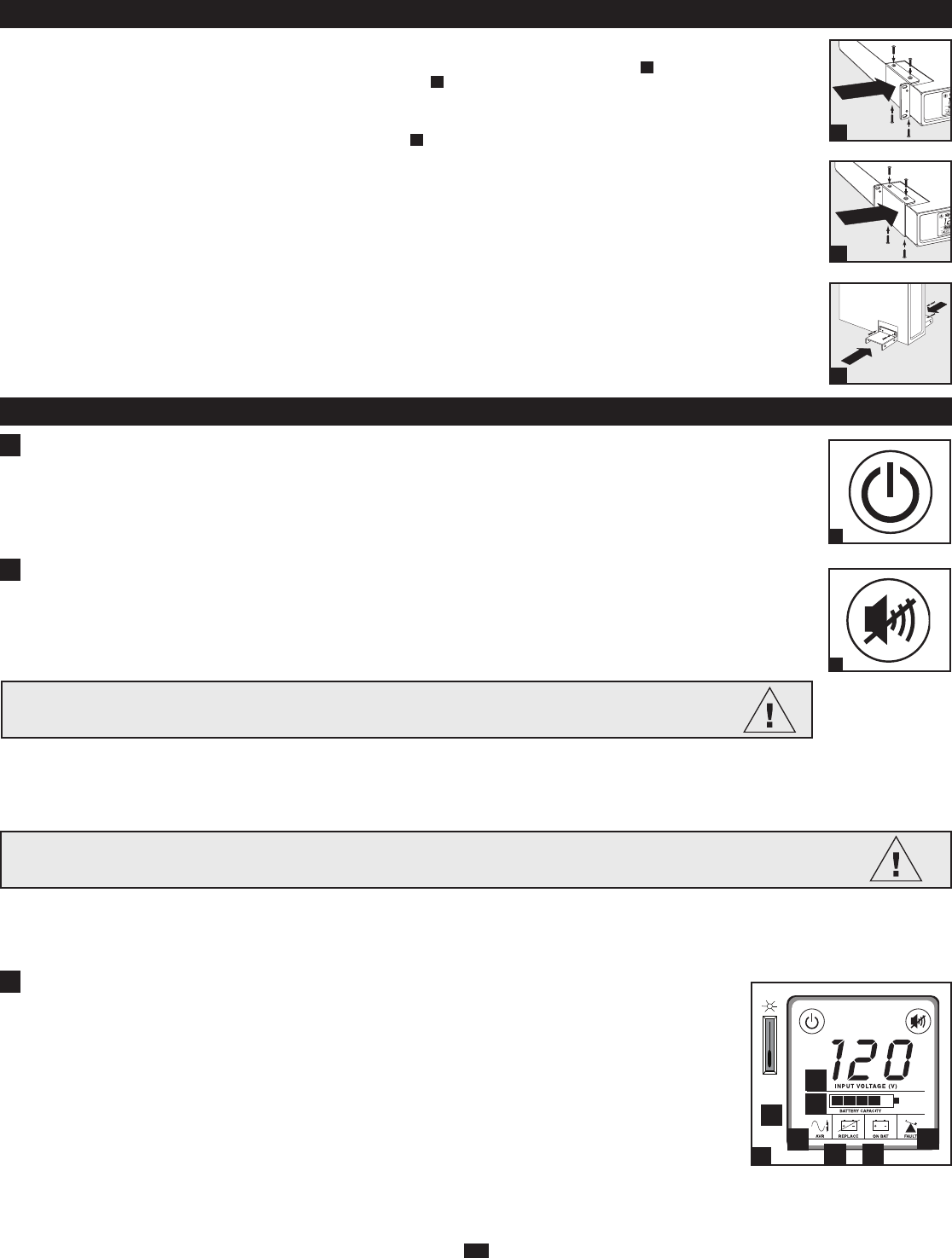
“ON/OFF” Button
• To turn the UPS on: Press and hold the ON/OFF button for several seconds until you hear a beep. If utility power is absent,
pressing the ON/OFF button will cold-start the UPS, i.e. turn it on and supply power from its battery.*
• To turn the UPS off: Press and hold the ON/OFF button for several seconds until you hear a beep. The UPS will be turned
off (completely deactivated).
* When the USP is cold-started, it will provide runtime proportionate to the level of charge of its battery.
“MUTE/TEST” Button
• To Silence (or “Mute”) UPS Alarms: briefly press and release the MUTE/TEST button. Note: continuous alarms (warning
you to immediately shut down connected equipment) cannot be silenced.
• To Run a Self-Test: with your UPS plugged in and turned on, press and hold the MUTE/TEST button for two seconds.
Continue holding the button until the alarm beeps several times and the UPS performs a self-test. See “Results of a Self-Test”
below. Note: you can leave connected equipment on during a self-test.
2
A
B
C
Basic Operation (Front Panel)
CAUTION! Do not unplug your UPS to test its battery.This will remove safe electrical grounding and may
introduce a damaging surge into your network connections.
ON/OFF Button
1
1.
2.
MUTE/TEST Button
2
Quick Installation
Results of a Self-Test: The test will last approximately 10 seconds as the UPS switches to battery to test its load capacity. All LCD Display icons will be illuminated
and the UPS alarm will sound.
• If the “FAULT” icon remains lit and the alarm continues to sound after the test, the outlets are overloaded. To clear the overload, unplug some of your equipment
from the outlets and run the self-test repeatedly until the “FAULT” icon is no longer lit and the alarm is no longer sounding.
• If the “REPLACE” icon remains lit and the alarm continues to sound after the test, the UPS batteries need to be recharged or replaced. Allow the UPS to
recharge continuously for 12 hours, and repeat the self-test. If the icon continues to illuminate after repeated self tests, contact Tripp Lite for service. Battery
replacement should only be performed by qualified service personnel. If the UPS requires battery replacement, Tripp Lite offers a complete line of replacement
batteries at www.tripplite.com.
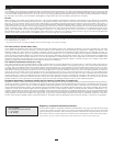
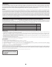
LCD Display
The LCD Display indicates a variety of UPS operational conditions. All descriptions apply when the UPS is plugged into an
AC outlet and turned on. The LCD Display can be rotated for easy viewing, regardless of whether the UPS is in a horizontal
or vertical (“tower”) position. To rotate the display, insert a small tool in the slots on the sides of the display to pop it out of
the UPS housing; rotate the display, and snap it back into the UPS housing.
3a) “Input Voltage” Meter: This meter measures, in real time, the AC voltage that the UPS system is receiving from the
utility wall outlet. Although the meter may occasionally display input voltages which stray (due to poor quality utility serv-
ice) outside the range of standard computer tolerance, rest assured that the UPS is designed (through the use of automatic
voltage regulation) to continuously supply connected equipment with stable, computer-grade output voltage. In the event
of a blackout (power loss), severe brownout (low power) or overvoltage (high power), the UPS will rely on its internal bat-
tery to supply computer-grade output voltage. The Input Voltage Meter can be used as a diagnostic tool to identify poor
quality input power. By plugging the UPS into different outlets within a facility, you can identify individual circuits that
are consistently providing low power, which can be caused by the combined equipment load demanding more power than
the circuit is designed to supply. If all circuits within a facility consistently provide low power, the facility may be served
by inadequate utility service or may be in an industrial or commercial area with an overburdened power grid.
CAUTION!
Any overload that is not corrected by the user immediately following a self-test may cause the UPS to shut
down and cease supplying output power in the event of a blackout or brownout.
3.
LCD Display
3
3a
3b
3c
3d 3e
3f
Dimmer
Switch
3g