


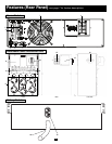
I/P BYPASS
BATTERY AC/DC DC/AC O/P
OFFON
MUTE SELECT
SETUP
10
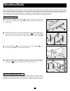
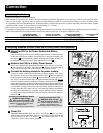
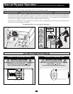
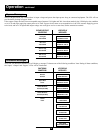
Manual Bypass Operation
(for power module maintenance or replacement)
The UPS system includes a self-contained power/battery module along with an independ-
ent, detachable PDU with a bypass switch. This switch allows qualified service personnel
to remove the detachable PDU from the power/battery module for routine maintenance
without disrupting power to connected loads. While this switch is set to “BYPASS”, con-
nected equipment will receive unfiltered AC utility power, but the equipment will not
receive battery power in the event of a blackout.
Note: If desired, an optional hardwire detachable PDU is also available separately from
Tripp Lite. Contact Tripp Lite for details.
WARNING! For qualified service personnel only. Failure to follow the bypass proce-
dure completely will not adequately power down the UPS power/battery module,
resulting in the continued risk of death or injury from potential contact with high
voltage. The UPS's power/battery module and detachable PDU are extremely heavy.
This procedure requires several people to perform.
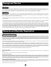
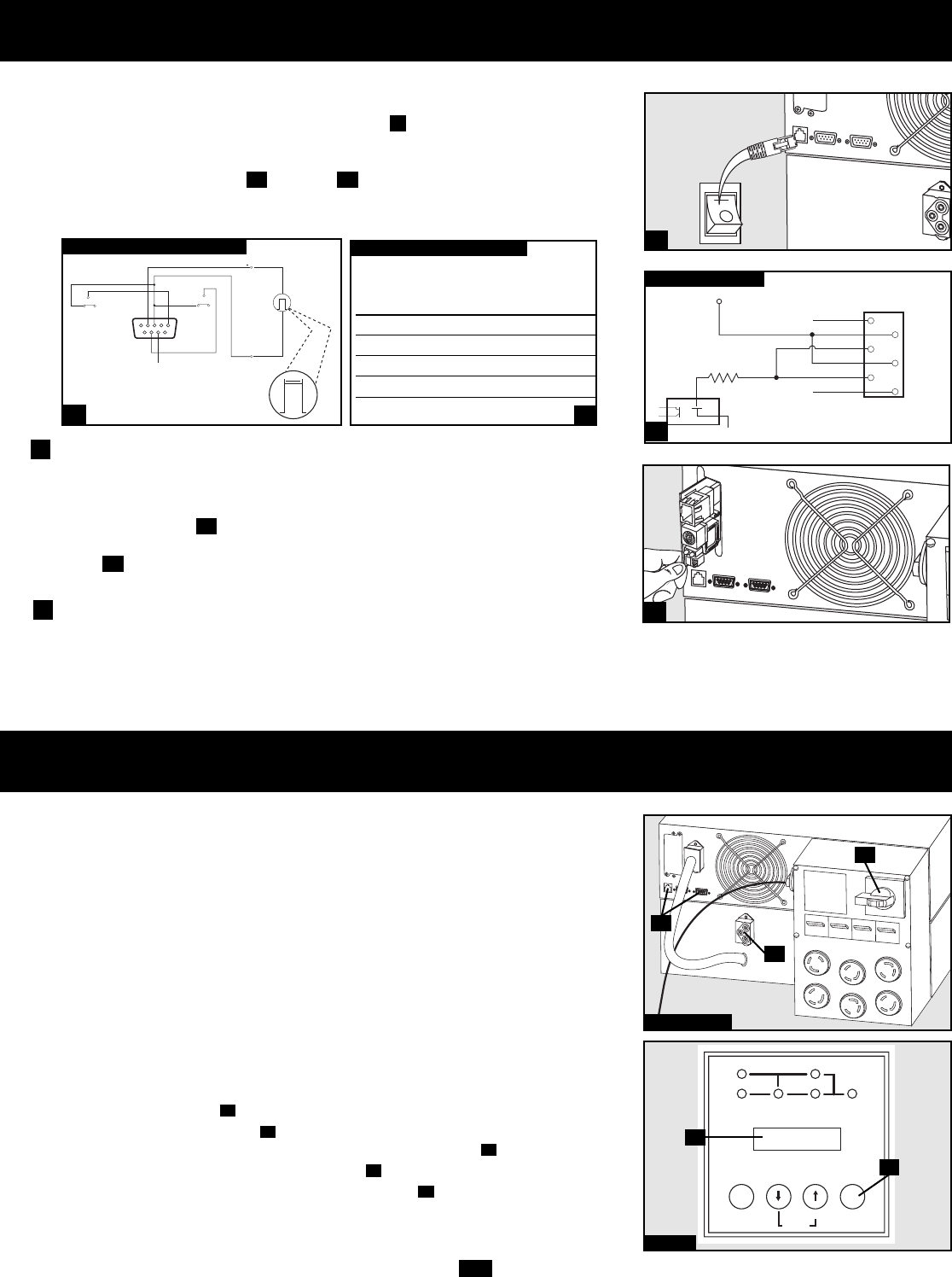
Step 2
D
C
UPS Power/Battery Module Removal
STEP 1. Disable PowerAlert Software and disconnect communication cables from the
communication ports on the UPS power/battery module.
STEP 2. Press UPS's “OFF” Button , if the UPS is powered, until you hear a beep and
see a “BYPASS MODE” message shown in the LCD Display .
STEP 3. Turn the detachable PDU's Bypass Switch to “BYPASS”.
STEP 4. If an external battery module is connected to the UPS , disconnect it from the UPS.
The UPS power/battery module is now safely powered down and it can be detached
from the PDU to perform maintenance/replacement.
E
B
D
C
A
Steps 1, 3 & 4
E
A
B
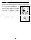
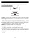
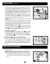
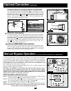
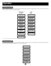
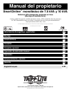
Contact-Closure Communication Connection
Use a user-supplied contact-closure DB9 cable to connect the power mod-
ule's Dry-Contact port to the communication port on your computer or other
equipment. This will allow basic contact-closure signals to be sent to and from
the UPS. Refer to diagram and table to determine the signals carried by
this port. Install on your computer the Tripp Lite PowerAlert Software appro-
priate to your computer's operating system.
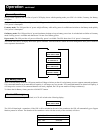
EPO Port Connection
This optional feature is only for those applications which require connection
to a facility’s Emergency Power Off (EPO) circuit. When the power module is
connected to this circuit, it enables emergency shutdown of the output. Using
the included cable , connect the power module’s EPO port to a user-sup-
plied remote switch. The pin assignments for the EPO port are shown in dia-
gram . Note: if there is a short between pins 2 and 3, 2 and 5, 4 and 5, or 3
and 4, the UPS system will power off.
Internal SNMP/WEB Card Insertion
Remove the small cover panel from the accessory slot to use optional acces-
sories to remotely monitor and control your UPS. Contact Tripp Lite Customer
Support at (773) 869-1234 for more information, including a list of available
SNMP, network management and connectivity products.
2b
2a
1d1c
B
1
2
3
4
5
6
X
12V
X
1K
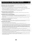
EPO PIN ASSIGNMENT
2
2a
2b
3
3
0
12 V
>2 sec
54321
9
8
7
6
NO
COM NC
lm in. > 3.3 mA
BACK-UP
REMOTE SHUTDOWN SIGNAL
FROM EXTERNAL
SIGNAL FROM COMPUTER
COM NC
LOW BATTERY
NO
MAXIMUM CAPACITY OF DRY CONTACT: AC250V/3A • DC30V/3A
DRY CONTACT INTERFACE DIAGRAM
UPS
Operating
Mode Pin 8,3 Pin 1,3 Pin 6,3
Normal OPEN OPEN *
Back Up CLOSE * *
Low Battery CLOSE CLOSE *
Fault * * CLOSE
* Inactive:may be in either state
DRY CONTACT INTERFACE TABLE
1c
1d
Optional Connection
continued