


5
Features
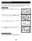
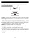
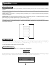
Before installing and operating your UPS, familiarize yourself with the location and function of the features of each component.
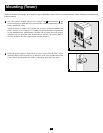
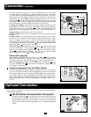
Power Module Front Panel Controls
1. LCD DISPLAY: This backlit (16 × 2 character) dot matrix display indicates a wide range of UPS operating conditions and diagnostic
data. It also displays UPS settings and options when the UPS is in setup mode.
2. ON/MUTE BUTTON: Press this button and hold it until you hear a beep to turn the UPS system’s inverter ON. If the UPS’s battery
alarm is sounding, press this button to silence it.
3. SCROLL DOWN/EXIT SETUP BUTTON: This button allows you to browse through different options and power readings on the
LCD display. Momentarily pressing it causes the LCD screen to display a different power reading (see “Operation”, pg. 12). Pressing it
and the SCROLL UP Button together puts the UPS in setup mode, where this button is used to scroll through setup options and to exit
setup mode.
4. SCROLL UP/SELECT BUTTON: This button allows you to browse through different options and power readings on the LCD dis-
play. Momentarily pressing it causes the LCD screen to display a different power reading (see “Operation”, pg. 12). Pressing it and the
SCROLL DOWN Button together puts the UPS in setup mode, where this button is used to select setup options.
5. OFF BUTTON: Press this button until you hear a beep to turn the UPS system’s inverter OFF.
6. O/P (OUTPUT) LED: This green light will illuminate to indicate your UPS is supplying AC power to connected equipment.
7. DC/AC (INVERTER) LED: This green light will illuminate to indicate the UPS’s DC/AC inverter is activated.
8. BYPASS LED: This green light will illuminate when the UPS is providing filtered mains power without engaging its converter or
inverter. If this LED is lit, connected equipment will not receive battery power in the event of a blackout.
9. AC/DC (Converter) LED: This green light will illuminate to indicate the UPS’s AC/DC converter is charging the connected battery pack(s).
10. BATTERY LED: This red light will illuminate when the UPS is discharging the battery to provide connected equipment with AC
power. An alarm will sound which can be silenced by pressing the ON/MUTE Button. This LED will remain lit after the alarm is
silenced.
11. I/P (INPUT) LED: This green light will illuminate to indicate an AC input supply is present.
12. ACCESS SLOTS: To rotate the controls, insert a flathead screwdriver into these slots and gently lever the panel out. Taking care not
to excessively twist or yank the cables connecting the controls to the rest of the UPS, turn the controls to the desired orientation and
reinsert them.
1
2 345
6879
10
11
12
12